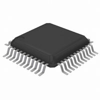
BH1414K-E2 Rohm Semiconductor, BH1414K-E2 Datasheet - Page 7

BH1414K-E2
Manufacturer Part Number
BH1414K-E2
Description
IC TRANSMITTER FM STEREO QFP44
Manufacturer
Rohm Semiconductor
Type
Transmitterr
Specifications of BH1414K-E2
Frequency
76MHz ~ 90MHz, 87.5MHz ~ 108MHz
Applications
Wireless Audio Link LSI
Modulation Or Protocol
FM
Power - Output
-7dBm
Current - Transmitting
29mA
Data Interface
PCB, Surface Mount
Antenna Connector
PCB, Surface Mount
Voltage - Supply
4.5 V ~ 5.5 V
Operating Temperature
-40°C ~ 85°C
Package / Case
44-QFP
Operating Frequency
110 MHz
Operating Supply Voltage
5 V
Maximum Operating Temperature
+ 85 C
Minimum Operating Temperature
- 40 C
Mounting Style
SMD/SMT
Lead Free Status / RoHS Status
Lead free / RoHS Compliant
Features
-
Memory Size
-
Data Rate - Maximum
-
Lead Free Status / Rohs Status
Lead free / RoHS Compliant
Other names
BH1414K-E2
BH1414K-E2TR
BH1414K-E2TR
Available stocks
Company
Part Number
Manufacturer
Quantity
Price
Company:
Part Number:
BH1414K-E2
Manufacturer:
INFINEON
Quantity:
2 300
Multimedia ICs
! ! ! ! Electrical characteristics (Unless otherwise noted, Ta = 25°C, V
Quiescent current
Channel separation
Total harmonic distortion
Channel balance
Input output gain 1
Input output gain 2
Input output gain 3
Limiter input level
LPF attenuation volume 1
LPF attenuation volume 2
LPF attenuation volume 3
Signal to noise ratio
Sub carrier rejection ratio
Pilot output level
Mute attenuation volume
Transmission output level
Transmission frequency
precision
"H" level input current
"L" level input current
"H" level output voltage
"L" level output voltage
"OFF" level leak current 1
"OFF" level leak current 2
"L" level output voltage
"OFF" level leak current
This product is not designed for protection against radioactive rays.
The specification of transmission output level be based on the Radio Law in every country and the area.
Parameter
V
Symbol
V
V
V
V
O(MUTE)
THD
SCR
I
I
Sep
O(LPF)1
O(LPF)2
O(LPF)3
C.B
S/N
V
∆f
V
G
G
G
IN(LIM)
V
V
V
I
OFF1
OFF2
I
OFF
I
I
IH
Q
OP
IL
OH
OL
OL
TX
V1
V2
V3
TX
V
CC
−100
−1.5
−1.0
Min.
−10
205
180
15
30
−4
+2
−2
55
84
−3
−
−
−
−
−
−
−
−
−
−
−1.0
V
CC
Typ.
260
−37
−49
−30
200
−68
0.1
0.5
0.3
0.2
21
45
−2
+4
−8
68
87
0
0
−
−
−
−
−
−0.3
Max.
+1.5
+1.5
325
−30
−35
−20
220
−60
100
0.3
1.0
1.0
1.0
1.0
29
+6
−6
90
+3
−
0
−
−
−
−
CC
=5.0V, Signal source : f
mVrms
mV
dBµV
Unit
kHz
mA
dB
dB
dB
dB
dB
dB
dB
dB
dB
dB
dB
µA
µA
nA
nA
µA
%
V
V
V
P-P
V
V
V
V
V
V
Output distortion at 3% for input
level
V
V
V
V
V
Pin19
V
f
f
Pin30, 31, 32, 33 V
Pin30, 31, 32, 33 V
Pin20 I
Pin20 I
Pin20 V
Pin20 V
Pin29 I
Pin29 V
TX
TX
IN
IN
IN
IN
IN
IN
IN
IN
IN
IN
IN
IN
=100MHz
=100MHz
=125mVrms, L→R, R→L
=125mVrms, L+R
=125mVrms, L+R
=125mVrms, EVR=0dB, L+R
=125mVrms, EVR=+6dB, L+R
=125mVrms, EVR=−6dB, L+R
=125mVrms, f=10kHz
=125mVrms, f=19kHz
=125mVrms, f=38kHz
=125mVrms, L+R
=125mVrms, L+R
=125mVrms, L+R
OUT
OUT
OUT
OUT
OUT
OUT
=−1.0mA
=1.0mA
=3.0mA
=5V
=GND
=5V
Conditions
IN
=400Hz)
IN
IN
=5V
=0V
BH1414K
Meaasurement
Fig.1
Fig.2
Fig.3
Fig.2
Fig.3
Fig.3
Fig.3
Fig.4
Fig.5
Fig.5
Fig.5
Fig.3
Fig.3
Fig.3
Fig.6
Fig.7
Fig.7
Fig.8
Fig.8
Fig.8
Fig.8
Fig.9
Fig.9
Fig.8
Fig.9
circuit


