ATAB5570 Atmel, ATAB5570 Datasheet - Page 12
ATAB5570
Manufacturer Part Number
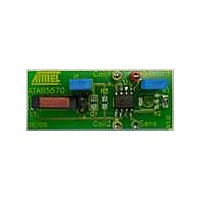
ATAB5570
Description
BOARD EVAL FOR ATAB5570
Manufacturer
Atmel
Type
Development kitr
Specifications of ATAB5570
Contents
Fully Assembled Evaluation Board
Product
RFID Transponders
For Use With/related Products
ATA5570
Lead Free Status / RoHS Status
Contains lead / RoHS non-compliant


Figure 5-6.
5.9
5.10
12
Password
Answer-on-request (AOR) Mode
Standard write
Direct access (PWD = 1)
Direct access (PWD = 0)
Page 0/1 regular read
AOR (wake-up command)
Reset command
Protected write
ATA5570 [Preliminary]
ATA5570 Command Formats
When password mode is active (PWD = 1), the first 32 bits after the opcode are regarded as the
password. They are compared bit-by-bit with the contents of block 7, starting at bit 1. If the com-
parison fails, the ATA5570 will not program the memory, instead it will restart in regular-read
mode once the command transmission is finished.
Note:
Each transmission of the direct access command (two opcode bits, 32 bits password, “0” bit plus
3 address bits = 38 bits) needs about 18 ms. Testing all possible combinations (about 4.3 billion)
would take about two years.
When the AOR bit is set, the ATA5570 does not start modulation in the regular-read mode after
loading configuration block 0. The tag waits for a valid AOR data stream (“wake-up command”)
from the reader before modulation is enabled. The wake-up command consists of the opcode
(“10”) followed by a valid password. The selected tag will remain active until the RF field is
turned off or a new command with a different password is transmitted which may address
another tag in the RF field.
In password mode, MAXBLK should be set to a value below 7 to prevent the password from being
transmitted by the ATA5570.
1p*
1p* L
1p *
1p*
1p*
OP
10
00
1
1
1
0
1
2 Addr
Password
Password
Password
0
Data
32
32
32
* p = page selector
32
L
0
2 Addr
1
2 Addr
0
0
Data
32
2 Addr
4863A–RFID–07/05
0
Related parts for ATAB5570
Image
Part Number
Description
Manufacturer
Datasheet
Request
R

Part Number:
Description:
DEV KIT FOR AVR/AVR32
Manufacturer:
Atmel
Datasheet:

Part Number:
Description:
INTERVAL AND WIPE/WASH WIPER CONTROL IC WITH DELAY
Manufacturer:
ATMEL Corporation
Datasheet:
Part Number:
Description:
Low-Voltage Voice-Switched IC for Hands-Free Operation
Manufacturer:
ATMEL Corporation
Datasheet:
Part Number:
Description:
MONOLITHIC INTEGRATED FEATUREPHONE CIRCUIT
Manufacturer:
ATMEL Corporation
Datasheet:
Part Number:
Description:
AM-FM Receiver IC U4255BM-M
Manufacturer:
ATMEL Corporation
Datasheet:
Part Number:
Description:
Monolithic Integrated Feature Phone Circuit
Manufacturer:
ATMEL Corporation
Datasheet:
Part Number:
Description:
Multistandard Video-IF and Quasi Parallel Sound Processing
Manufacturer:
ATMEL Corporation
Datasheet:
Part Number:
Description:
High-performance EE PLD
Manufacturer:
ATMEL Corporation
Datasheet:
Part Number:
Description:
8-bit Flash Microcontroller
Manufacturer:
ATMEL Corporation
Datasheet:
Part Number:
Description:
2-Wire Serial EEPROM
Manufacturer:
ATMEL Corporation
Datasheet: