123NQ080 Vishay, 123NQ080 Datasheet - Page 2
123NQ080
Manufacturer Part Number
123NQ080
Description
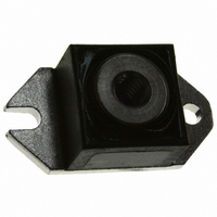
DIODE SCHOTTKY 80V 120A HALF-PAK
Manufacturer
Vishay
Datasheet
1.123NQ100.pdf
(5 pages)
Specifications of 123NQ080
Voltage - Forward (vf) (max) @ If
910mV @ 120A
Current - Reverse Leakage @ Vr
3mA @ 80V
Current - Average Rectified (io) (per Diode)
120A
Voltage - Dc Reverse (vr) (max)
80V
Diode Type
Schottky
Speed
Fast Recovery =< 500ns, > 200mA (Io)
Diode Configuration
Single
Mounting Type
Chassis Mount
Package / Case
D-67 HALF-PAK
Lead Free Status / RoHS Status
Lead free / RoHS Compliant
Reverse Recovery Time (trr)
-
Other names
*123NQ080
VS-123NQ080
VS-123NQ080
VS123NQ080
VS123NQ080
VS-123NQ080
VS-123NQ080
VS123NQ080
VS123NQ080
Available stocks
Company
Part Number
Manufacturer
Quantity
Price

Part Number:
123NQ080
Quantity:
99


123NQ...(R) Series
Electrical Specifications
Bulletin PD-2.250 rev. C 05/02
2
Voltage Ratings
Absolute Maximum Ratings
Thermal-Mechanical Specifications
I
I
E
I
T
T
R
R
wt
T
V
I
C
L
dv/dt Max. Voltage Rate of Change
V
V
FSM
F(AV)
AR
RM
S
J
stg
AS
thJC
thCS
FM
R
RWM
T
Parameters
Max. Average Forward Current
* See Fig. 5
Max. Peak One Cycle Non-Repetitive
Surge Current * See Fig. 7
Non-Repetitive Avalanche Energy
Repetitive Avalanche Current
Part number
Max. DC Reverse Voltage (V)
Max. Working Peak Reverse Voltage (V)
Parameters
Max. Forward Voltage Drop
* See Fig. 1
Max. Reverse Leakage Current (1)
* See Fig. 2
Max. Junction Capacitance
Typical Series Inductance
(Rated V
Parameters
Max. Junction Temperature Range
Max. Storage Temperature Range
Max. Thermal Resistance Junction
to Case
Typical Thermal Resistance, Case to
Heatsink
Approximate Weight
Mounting Torque
Terminal Torque
Case Style
R
)
Min.
Max.
Min.
Max.
(1)
-55 to 175
-55 to 175
123NQ Units
25.6 (0.9) g (oz.)
123NQ Units
123NQ Units
HALF PAK Module
16,000
40 (35)
58 (50)
58 (50)
86 (75)
10000
2650
2100
0.91
1.08
0.74
0.88
0.40
0.15
120
7.0
40
15
1
3
Kg-cm
(Ibf-in)
°C/W
°C/W
V/ µs
mA
mA
mJ
nH
pF
°C
°C
A
V
V
V
V
A
A
123NQ080
50% duty cycle @ T
10ms Sine or 6ms Rect. pulse
T
Current decaying linearly to zero in 1 µsec
Frequency limited by T
DC operation
Mounting surface , smooth and greased
Non-lubricated threads
5µs Sine or 3µs Rect. pulse
@ 120A
@ 240A
T
T
V
From top of terminal hole to mounting plane
@ 120A
@ 240A
J
J
J
80
R
= 25 °C, I
= 25 °C
= 125 °C
= 5V
DC
, (test signal range 100Khz to 1Mhz) 25 °C
AS
Conditions
Conditions
Conditions
= 1 Amps, L = 30 mH
* See Fig. 4
(1) Pulse Width < 300µs, Duty Cycle < 2%
V
T
T
123NQ090
J
J
R
C
= 25 °C
= 125 °C
= 121° C, rectangular wave form
= rated V
J
90
max. V
R
A
= 1.5 x V
Following any rated
load condition and
with rated V
123NQ100
R
www.irf.com
typical
100
RRM
applied
Related parts for 123NQ080
Image
Part Number
Description
Manufacturer
Datasheet
Request
R

Part Number:
Description:
357-036-542-201 CARDEDGE 36POS DL .156 BLK LOPRO
Manufacturer:
Vishay
Datasheet:
Part Number:
Description:
357-036-542-201 CARDEDGE 36POS DL .156 BLK LOPRO
Manufacturer:
Vishay
Datasheet:
Part Number:
Description:
357-036-542-201 CARDEDGE 36POS DL .156 BLK LOPRO
Manufacturer:
Vishay
Datasheet:
Part Number:
Description:
357-036-542-201 CARDEDGE 36POS DL .156 BLK LOPRO
Manufacturer:
Vishay
Datasheet:
Part Number:
Description:
357-036-542-201 CARDEDGE 36POS DL .156 BLK LOPRO
Manufacturer:
Vishay
Datasheet:
Part Number:
Description:
357-036-542-201 CARDEDGE 36POS DL .156 BLK LOPRO
Manufacturer:
Vishay
Datasheet:
Part Number:
Description:
357-036-542-201 CARDEDGE 36POS DL .156 BLK LOPRO
Manufacturer:
Vishay
Datasheet:
Part Number:
Description:
357-036-542-201 CARDEDGE 36POS DL .156 BLK LOPRO
Manufacturer:
Vishay
Datasheet:
Part Number:
Description:
357-036-542-201 CARDEDGE 36POS DL .156 BLK LOPRO
Manufacturer:
Vishay
Datasheet:
Part Number:
Description:
357-036-542-201 CARDEDGE 36POS DL .156 BLK LOPRO
Manufacturer:
Vishay
Datasheet:
Part Number:
Description:
357-036-542-201 CARDEDGE 36POS DL .156 BLK LOPRO
Manufacturer:
Vishay
Datasheet:
Part Number:
Description:
357-036-542-201 CARDEDGE 36POS DL .156 BLK LOPRO
Manufacturer:
Vishay
Datasheet:
Part Number:
Description:
357-036-542-201 CARDEDGE 36POS DL .156 BLK LOPRO
Manufacturer:
Vishay
Datasheet:
Part Number:
Description:
357-036-542-201 CARDEDGE 36POS DL .156 BLK LOPRO
Manufacturer:
Vishay
Datasheet:
Part Number:
Description:
357-036-542-201 CARDEDGE 36POS DL .156 BLK LOPRO
Manufacturer:
Vishay
Datasheet: