IGBT 600V SOT-227B


IXGN320N60A3

Manufacturer Part NumberIXGN320N60A3
DescriptionIGBT 600V SOT-227B
ManufacturerIXYS
SeriesGenX3™
IXGN320N60A3 datasheets

Availability: In stock

International delivery:

Warranty: 60 days

Shipping & payment terms

Added to cart


Specifications of IXGN320N60A3

Igbt TypePTConfigurationSingle
Voltage - Collector Emitter Breakdown (max)600VVce(on) (max) @ Vge, Ic1.25V @ 15V, 100A
Current - Collector (ic) (max)320ACurrent - Collector Cutoff (max)150µA
Input Capacitance (cies) @ Vce18nF @ 25VPower - Max735W
InputStandardNtc ThermistorNo
Mounting TypeChassis MountPackage / CaseSOT-227, miniBLOC
Channel TypeNCollector-emitter Voltage600V
Collector Current (dc) (max)320AGate To Emitter Voltage (max)±20V
Package TypeSOT-227BPin Count4
MountingScrewOperating Temperature (min)-55
Operating Temperature (max)150COperating Temperature ClassificationMilitary
Vces, (v)600Ic25, Tc=25°c, Igbt, (a)320
Ic110, Tc=110°c, Igbt, (a)170Vce(sat), Max, Tj=25°c, Igbt, (v)1.25
Rthjc, Max, Igbt, (°c/w)0.17Package StyleSOT-227B
Lead Free Status / RoHS StatusLead free / RoHS Compliant  
1
Page 1
2
Page 2
3
Page 3
4
Page 4
5
Page 5
Page 1/5

Download datasheet (168Kb)Embed
Next
GenX3
600V IGBT
TM
Ultra-Low-Vsat PT IGBT for
up to 5kHz Switching
Symbol
Test Conditions
V
T
= 25°C to 150°C
CES
J
V
T
= 25°C to 150°C, R
CGR
J
V
Continuous
GES
V
Transient
GEM
I
T
= 25°C (Chip Capability)
C25
C
I
T
= 110°C
C110
C
I
Terminal Current Limit
LRMS
I
T
= 25°C, 1ms
CM
C
SSOA
V
= 15V, T
= 125°C, R
GE
VJ
(RBSOA)
Clamped Inductive Load
P
T
= 25°C
C
C
T
J
T
JM
T
stg
V
50/60Hz
t = 1min
ISOL
≤ 1mA
I
t = 1s
ISOL
M
Mounting Torque
d
Terminal Connection Torque (M4)
Weight
Symbol
Test Conditions
(T
= 25°C, Unless Otherwise Specified)
J
BV
I
= 1mA, V
= 0V
CES
C
GE
V
I
= 4mA, V
= V
GE(th)
C
CE
GE
I
V
= V
, V
= 0V
CES
CE
CES
GE
I
V
= 0V, V
= ±20V
GES
CE
GE
V
I
= 100A, V
= 15V, Note 1
CE(sat)
C
GE
I
= 320A
C
© 2009 IXYS CORPORATION, All Rights Reserved
IXGN320N60A3
Maximum Ratings
600
= 1MΩ
600
GE
±20
±30
320
170
200
1200
= 1Ω
I
= 320
G
CM
@0.8 • V
CES
735
-55 ... +150
150
-55 ... +150
2500
3000
1.5/13
1.3/11.5
30
Characteristic Values
Min.
Typ.
600
3.0
T
= 125°C
J
1.05
1.46
V
= 600V
CES
I
= 320A
C25
≤ ≤ ≤ ≤ ≤ 1.25V
V
CE(sat)
E
SOT-227B, miniBLOC
E153432
V
V
G
V
V
A
A
A
G = Gate, C = Collector, E = Emitter
A
A
Either Emitter Terminal Can Be Used
as Main or Kelvin Emitter
W
Features
°C
°C
Optimized for Low Conduction Losses
°C
High Avalanche Capability
V~
Isolation Voltage 3000
V~
International Standard Package
Nm/lb.in.
Nm/lb.in.
Advantages
g
High Power Density
Low Gate Drive Requirement
Applications
Max.
Power Inverters
V
UPS
Motor Drives
5.0
V
SMPS
150 μA
PFC Circuits
1.5 mA
Battery Chargers
Welding Machines
±400 nA
Lamp Ballasts
Inrush Current Protection Circuits
1.25
V
V
E
E
C
V~
DS99576C(12/09)

IXGN320N60A3 Summary of contents

  • Page 1

    ... CES CE CES 0V ±20V GES 100A 15V, Note 1 CE(sat 320A C © 2009 IXYS CORPORATION, All Rights Reserved IXGN320N60A3 Maximum Ratings 600 = 1MΩ 600 GE ±20 ±30 320 170 200 1200 = 1Ω 320 G CM @0.8 • V CES 735 -55 ... +150 150 -55 ... +150 2500 3000 1.5/13 1 ...

  • Page 2

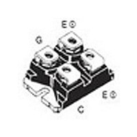
    ... CES 195 63 68 290 740 62 77 330 1540 0.05 4,931,844 5,049,961 5,237,481 6,162,665 5,017,508 5,063,307 5,381,025 6,259,123 B1 5,034,796 5,187,117 5,486,715 6,306,728 B1 IXGN320N60A3 SOT-227B miniBLOC (IXGN) Max screws (4x) supplied 0.17 °C/W °C/W 6,404,065 B1 6,683,344 6,727,585 7,005,734 B2 6,534,343 6,710,405 B2 6,759,692 ...

  • Page 3

    ... CE(sat 160A 80A C 75 100 125 150 25ºC - 40ºC 5.5 6.0 6.5 7.0 IXGN320N60A3 Fig. 2. Output Characteristics @ 0.0 0.2 0.4 0.6 0 Volts CE Fig. 4. Collector-to-Emitter Voltage vs. Gate-to-Emitter Voltage 3.2 2.8 2 320A C 160A 2.0 80A 1.6 1 ...

  • Page 4

    ... IXYS Reserves the Right to Change Limits, Test Conditions, and Dimensions. 100,000 10,000 1,000 100 0 400 500 600 1.000 0.100 0.010 0.001 0.00001 400 450 500 550 600 IXGN320N60A3 Fig. 8. Capacitance MHz C ies C oes C res Volts CE Fig. 10. Maximum Transient Thermal Impedance 0.0001 0.001 0.01 ...

  • Page 5

    ... IXGN320N60A3 Fig. 12. Resistive Turn-on Rise Time vs. Collector Current R = 1Ω 15V 400V 125º 25ºC J 100 120 140 160 180 ...