PM50CLA120 Powerex Inc, PM50CLA120 Datasheet - Page 2
PM50CLA120
Manufacturer Part Number
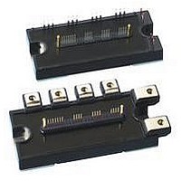
PM50CLA120
Description
MOD IPM L-SER 6PAC IPM 1200V 50A
Manufacturer
Powerex Inc
Series
Intellimod™r
Type
IGBTr
Datasheet
1.PM50CLA120.pdf
(4 pages)
Specifications of PM50CLA120
Configuration
3 Phase Inverter
Current
50A
Voltage
1200V
Voltage - Isolation
2500VDC
Package / Case
Module
Power Dissipation Pd
369W
Collector Emitter Voltage V(br)ceo
1.2kV
Continuous Collector Current Ic
50A
Collector Emitter Saturation Voltage Vce(sat)
2.3V
Output Current
50A
Operating Voltage
1.2kV
Distributorinventory
View
Circuit Configuration
6-Pac
Package
120x55mm - A
Rohs Compliant
Yes
Recommended Accessory
BP7B-LS
Lead Free Status / RoHS Status
Lead free / RoHS Compliant
For Use With
BP7B-LS - KIT DEV INTERFACE FOR IPMBP7A-LS - KIT DEV INTERFACE FOR IPM
Lead Free Status / RoHS Status
Lead free / RoHS Compliant, Lead free / RoHS Compliant
Available stocks
Company
Part Number
Manufacturer
Quantity
Price
Company:

Part Number:
PM50CLA120
Manufacturer:
TOSHIBA
Quantity:
1 001
Part Number:
PM50CLA120
Manufacturer:
MIT
Quantity:
20 000
Part Number:
PM50CLA120
Quantity:
60


2
Powerex, Inc., 200 E. Hillis Street, Youngwood, Pennsylvania 15697-1800 (724) 925-7272
PM50CLA120
Intellimod™ L-Series
Three Phase IGBT Inverter
50 Amperes/1200 Volts
Absolute Maximum Ratings, T
Characteristics
Power Device Junction Temperature
Storage Temperature
Mounting Torque, M5 Mounting Screws
Mounting Torque, M5 Main Terminal Screws
Module Weight (Typical)
Supply Voltage, Surge (Applied between P - N)
Self-protection Supply Voltage Limit (Short Circuit protection Capability)*
Isolation Voltage, AC 1 minute, 60Hz Sinusoidal
*VD = 13.5 ~ 16.5V, Inverter Part, Tj = 125°C
IGBT Inverter Sector
Collector-Emitter Voltage (V
Collector Current (T
Peak Collector Current (T
Collector Dissipation (T
Control Sector
Supply Voltage (Applied between V
Input Voltage (Applied between U
Fault Output Supply Voltage
(Applied between U
Fault Output Current (U
Electrical and Mechanical Characteristics, T
Characteristics
IGBT Inverter Sector
Collector-Emitter Cutoff Current
Diode Forward Voltage
Collector-Emitter Saturation Voltage
Inductive Load Switching Times
FO
C
= 25°C)
-V
C
FO
UPC
C
= 25°C)
, V
D
= 25°C)
FO
, V
= 15V, V
FO
, W
P
-V
-V
FO
UP1
VPC
UPC
, F
CIN
-V
j
O
, W
UPC
, V
= 25°C unless otherwise specified
= 15V)
Terminals)
P
FO
-V
, V
V
-V
Symbol
VPC
VP1
t
t
CE(sat)
I
C(on)
C(off)
V
CES
WPC
t
t
t
on
off
EC
rr
, W
-V
, F
VPC
P
-V
O
-V
, V
WPC
j
= 25°C unless otherwise specified
NC
WP1
, U
)
V
V
-I
CE
-V
V
V
N
CE
C
D
D
- V
WPC
V
= V
= 50A, V
= 15V, V
= 15V, V
D
= V
N
V
= 15V, V
- W
CC
CES
, V
CES
Test Conditions
N1
N
= 600V, I
, V
T
T
-V
T
, V
CIN
j
j
-V
CIN
CIN
j
= 125°C
= 125°C
D
NC
= 25°C
D
NC
CIN
= 15V, T
= 15V, V
= 15V, T
)
= 0V, I
= 0V, I
)
= 0 ⇔ 15V
C
= 50A
V
V
C
C
CC(surge)
Symbol
CC(prot.)
D
j
V
j
V
V
= 50A,
= 50A,
±I
V
T
= 125°C
±I
I
= 25°C
P
V
CES
—
—
—
FO
= 15V
T
ISO
CIN
stg
FO
CP
C
D
C
j
Min.
0.5
—
—
—
—
—
—
—
—
—
PM50CLA120
-20 to 150
-40 to 125
1000
2500
1200
380
800
100
369
31
31
50
20
20
20
20
Typ.
2.5
1.8
1.9
1.0
0.5
0.4
2.0
0.7
—
—
Max.
1.0
3.5
2.3
2.4
2.5
0.8
1.0
3.0
1.2
10
Amperes
Amperes
Grams
Watts
Units
Volts
Volts
Volts
Volts
Volts
Volts
Volts
in-lb
in-lb
mA
°C
°C
Units
Volts
Volts
Volts
mA
mA
µs
µs
µs
µs
µs
Related parts for PM50CLA120
Image
Part Number
Description
Manufacturer
Datasheet
Request
R

Part Number:
Description:
32-50 WATTS DC/DC SINGLE - DUAL
Manufacturer:
POWERBOX [Powerbox]
Datasheet:

Part Number:
Description:
Manufacturer:
Powerex Inc
Datasheet:
Part Number:
Description:
Manufacturer:
Powerex Inc
Datasheet:
Part Number:
Description:
Manufacturer:
Powerex Inc
Datasheet:
Part Number:
Description:
Manufacturer:
Powerex Inc
Datasheet:
Part Number:
Description:
Manufacturer:
Powerex Inc
Datasheet:
Part Number:
Description:
Manufacturer:
Powerex Inc
Datasheet:
Part Number:
Description:
Manufacturer:
Powerex Inc
Datasheet:
Part Number:
Description:
Manufacturer:
Powerex Inc
Datasheet:
Part Number:
Description:
Manufacturer:
Powerex Inc
Datasheet:
Part Number:
Description:
Manufacturer:
Powerex Inc
Datasheet:
Part Number:
Description:
Manufacturer:
Powerex Inc
Datasheet:
Part Number:
Description:
Manufacturer:
Powerex Inc
Datasheet:
Part Number:
Description:
Manufacturer:
Powerex Inc
Datasheet: