P402KW Vishay, P402KW Datasheet - Page 5
P402KW
Manufacturer Part Number
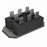
P402KW
Description
SCR HY-BRIDGE 600V 40A PACE-PAK
Manufacturer
Vishay
Specifications of P402KW
Structure
Bridge, Single Phase - SCRs/Diodes (Layout 1)
Number Of Scrs, Diodes
2 SCRs, 2 Diodes
Voltage - Off State
600V
Current - Gate Trigger (igt) (max)
60mA
Current - On State (it (rms)) (max)
40A (DC)
Current - Non Rep. Surge 50, 60hz (itsm)
385A, 400A
Current - Hold (ih) (max)
130mA
Mounting Type
Chassis Mount
Package / Case
6-PACE-PAK
Lead Free Status / RoHS Status
Lead free / RoHS Compliant
Current - On State (it (av)) (max)
-
Lead Free Status / RoHS Status
Lead free / RoHS Compliant, Lead free / RoHS Compliant
Other names
*P402KW


www.irf.com
130
120
110
100
30
25
20
15
10
90
80
70
5
0
Fig. 2 - On-state Power Loss Characteristics
0
0
Fig. 4 - Current Ratings Characteristics
120
100
Per Module
5
P400 Series
80
60
40
20
RMS Limit
0
Average On-state Current (A)
0
10 15 20 25 30 35
Fully Turned-on
180°
120°
Total Output Current (A)
5
90°
60°
30°
5
10
Total Output Current (A)
Fig. 1 - Current Ratings Nomogram (1 Module Per Heatsink)
10
(Sine)
180°
15
Conduction angle
(Sine)
P400 Series
T = 125°C
Per Junction
180°
J
20
15
(Rect)
180°
P400 Series
T = 125°C
J
25
40 45
30
20
35
40
0
Maximum Allowable Ambient Temperature (°C)
25
1000
100
40
35
30
25
20
15
10
10
Fig. 5 - On-state Voltage Drop Characteristics
50
5
0
1
Fig. 3 - On-state Power Loss Characteristics
0.5
0
RMS Limit
T = 25 °C
J
Instantaneous On-state Voltage (V)
1
5
75
Average On-sta te Current (A)
180°
120°
DC
90°
60°
30°
1.5
10
Bulletin I2776 rev. E 04/99
100
2
15
2.5
P400 Series
125
P400 Series
Per Junction
20
3
Conduction Period
P400 Series
T = 125°C
Per Junction
T = 125 °C
J
3.5
J
25
4
30
4.5
5
35
5
Related parts for P402KW
Image
Part Number
Description
Manufacturer
Datasheet
Request
R

Part Number:
Description:
SCR HY-BRIDGE 600V 40A PACE-PAK
Manufacturer:
Vishay
Datasheet:

Part Number:
Description:
357-036-542-201 CARDEDGE 36POS DL .156 BLK LOPRO
Manufacturer:
Vishay
Datasheet:
Part Number:
Description:
357-036-542-201 CARDEDGE 36POS DL .156 BLK LOPRO
Manufacturer:
Vishay
Datasheet:
Part Number:
Description:
357-036-542-201 CARDEDGE 36POS DL .156 BLK LOPRO
Manufacturer:
Vishay
Datasheet:
Part Number:
Description:
357-036-542-201 CARDEDGE 36POS DL .156 BLK LOPRO
Manufacturer:
Vishay
Datasheet:
Part Number:
Description:
357-036-542-201 CARDEDGE 36POS DL .156 BLK LOPRO
Manufacturer:
Vishay
Datasheet:
Part Number:
Description:
357-036-542-201 CARDEDGE 36POS DL .156 BLK LOPRO
Manufacturer:
Vishay
Datasheet:
Part Number:
Description:
357-036-542-201 CARDEDGE 36POS DL .156 BLK LOPRO
Manufacturer:
Vishay
Datasheet:
Part Number:
Description:
357-036-542-201 CARDEDGE 36POS DL .156 BLK LOPRO
Manufacturer:
Vishay
Datasheet:
Part Number:
Description:
357-036-542-201 CARDEDGE 36POS DL .156 BLK LOPRO
Manufacturer:
Vishay
Datasheet:
Part Number:
Description:
357-036-542-201 CARDEDGE 36POS DL .156 BLK LOPRO
Manufacturer:
Vishay
Datasheet:
Part Number:
Description:
357-036-542-201 CARDEDGE 36POS DL .156 BLK LOPRO
Manufacturer:
Vishay
Datasheet:
Part Number:
Description:
357-036-542-201 CARDEDGE 36POS DL .156 BLK LOPRO
Manufacturer:
Vishay
Datasheet:
Part Number:
Description:
357-036-542-201 CARDEDGE 36POS DL .156 BLK LOPRO
Manufacturer:
Vishay
Datasheet:
Part Number:
Description:
357-036-542-201 CARDEDGE 36POS DL .156 BLK LOPRO
Manufacturer:
Vishay
Datasheet: