VSKT230-12 Vishay, VSKT230-12 Datasheet - Page 2
VSKT230-12
Manufacturer Part Number
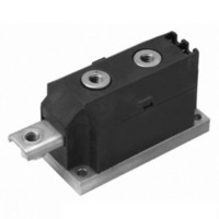
VSKT230-12
Description
SCR DBL HISCR 1200V 230A MAGNPAK
Manufacturer
Vishay
Datasheet
1.VSKL230-12.pdf
(8 pages)
Specifications of VSKT230-12
Structure
Series Connection - All SCRs
Number Of Scrs, Diodes
2 SCRs
Voltage - Off State
1200V
Current - Gate Trigger (igt) (max)
200mA
Current - On State (it (av)) (max)
230A
Current - On State (it (rms)) (max)
510A
Current - Non Rep. Surge 50, 60hz (itsm)
7500A, 7850A
Current - Hold (ih) (max)
500mA
Mounting Type
Chassis Mount
Package / Case
3-MAGN-A-PAK™
Mounting Style
Screw
Lead Free Status / RoHS Status
Contains lead / RoHS non-compliant
Other names
*IRKT230-12
IRKT230-12
IRKT230-12
IRKT230-12
IRKT230-12


VSK.230..PbF Series
Vishay Semiconductors
www.vishay.com
2
ON-STATE CONDUCTION
PARAMETER
Maximum average on-state current
at case temperature
Maximum RMS on-state current
Maximum peak, one-cycle on-state
non-repetitive, surge current
Maximum I
Maximum I
Low level value or threshold voltage
High level value of threshold voltage
Low level value on-state slope resistance
High level value on-state slope
resistance
Maximum on-state voltage drop
Maximum holding current
Maximum latching current
SWITCHING
PARAMETER
Typical delay time
Typical rise time
Typical turn-off time
BLOCKING
PARAMETER
Maximum peak reverse and
off-state leakage current
RMS insulation voltage
Critical rate of rise of off-state voltage
2
2
t for fusing
√t for fusing
DiodesAmericas@vishay.com, DiodesAsia@vishay.com,
For technical questions within your region, please contact one of the following:
(MAGN-A-PAK Power Modules), 230 A
SYMBOL
SYMBOL
SYMBOL
V
V
I
dV/dt
I
T(RMS)
I
I
V
I
RRM,
T(TO)1
T(TO)2
V
DRM
T(AV)
I
TSM
I
2
r
r
t
t
I
I
t
INS
2
TM
t1
t2
H
d
q
√t
L
r
t
SCR/SCR and SCR/Diode
T
50 Hz, circuit to base, all terminals shorted, 25 °C, 1 s
T
T
V
I
V
180° conduction, half sine wave
As AC switch
t = 10 ms
t = 8.3 ms
t = 10 ms
t = 8.3 ms
t = 10 ms
t = 8.3 ms
t = 10 ms
t = 8.3 ms
t = 0.1 ms to 10 ms, no voltage reapplied
(16.7 % x π x I
T
(I > π x I
(16.7 % x π x I
T
(I > π x I
I
average power = V
Anode supply = 12 V, initial I
Anode supply = 12 V, resistive load = 1 Ω,
gate pulse: 10 V, 100 μs, T
TM
TM
J
J
J
J
J
d
R
= 25 °C, gate current = 1 A dI
= T
= T
= T
= T
= 0.67 % V
= 50 V; dV/dt = 20 V/μs; gate 0 V, 100 Ω
= 300 A; dI/dt = 15 A/μs; T
= π x I
J
J
J
J
maximum
maximum, exponential to 67 % rated V
maximum
maximum
T(AV)
T(AV)
T(AV)
< I < π x I
< I < π x I
, T
DRM
T(AV)
T(AV)
TEST CONDITIONS
TEST CONDITIONS
TEST CONDITIONS
J
= T
No voltage
reapplied
100 % V
reapplied
No voltage
reapplied
100 % V
reapplied
< I < π x I
< I < π x I
T(TO)
J
T(AV)
T(AV)
maximum, 180° conduction,
x I
), T
), T
T(AV)
J
RRM
RRM
= 25 °C
T(AV)
T(AV)
DiodesEurope@vishay.com
T
J
J
J
= 30 A, T
= T
= T
+ r
= T
g
),
),
/dt = 1 A/μs
f
J
J
x (I
J
maximum
maximum
maximum;
Sinusoidal
half wave,
initial T
T
T(RMS)
J
maximum
J
= 25 °C
)
J
2
=
DRM
50 to 150
VALUES
VALUES
VALUES
Document Number: 93053
3000
1000
7500
7850
6300
6600
2800
1000
1.03
1.07
0.77
0.73
1.59
230
510
280
256
198
181
500
1.0
2.0
85
50
Revision: 02-Jul-10
UNITS
UNITS
UNITS
kA
kA
V/μs
mΩ
mA
mA
°C
μs
A
A
V
V
V
2
2
√s
s
Related parts for VSKT230-12
Image
Part Number
Description
Manufacturer
Datasheet
Request
R

Part Number:
Description:
SCR/SCR and SCR/Diode (MAGN-A-PAK Power Modules), 230 A
Manufacturer:
VISHAY [Vishay Siliconix]
Datasheet:

Part Number:
Description:
SCR DBL HISCR 800V 230A MAGNAPAK
Manufacturer:
Vishay
Datasheet:
Part Number:
Description:
SCR DBL HISCR 1400V 230A MAGNPAK
Manufacturer:
Vishay
Datasheet:
Part Number:
Description:
SCR DBL HISCR 1600V 230A MAGNPAK
Manufacturer:
Vishay
Datasheet:
Part Number:
Description:
SCR DBL HISCR 2000V 230A MAGNPAK
Manufacturer:
Vishay
Datasheet:

Part Number:
Description:
SCR Modules 230 Amp 1600 Volt 7850 Amp IT(RMS)
Manufacturer:
Vishay
Datasheet:
Part Number:
Description:
SCR Modules 230 Amp 2000 Volt 7850 Amp IT(RMS)
Manufacturer:
Vishay
Datasheet:
Part Number:
Description:
SCR Modules 230 Amp 1400 Volt 7850 Amp IT(RMS)
Manufacturer:
Vishay
Datasheet:
Part Number:
Description:
SCR Modules 230 Amp 1600 Volt 7850 Amp IT(RMS)
Manufacturer:
Vishay
Datasheet:
Part Number:
Description:
SCR Modules 230 Amp 800 Volt 7850 Amp IT(RMS)
Manufacturer:
Vishay
Datasheet:
Part Number:
Description:
SCR Modules 230 Amp 1400 Volt 7850 Amp IT(RMS)
Manufacturer:
Vishay
Datasheet:
Part Number:
Description:
SCR Modules 230 Amp 1200 Volt 7850 Amp IT(RMS)
Manufacturer:
Vishay
Datasheet:
Part Number:
Description:
SCR Modules 230 Amp 400 Volt 7850 Amp IT(RMS)
Manufacturer:
Vishay
Datasheet:
Part Number:
Description:
357-036-542-201 CARDEDGE 36POS DL .156 BLK LOPRO
Manufacturer:
Vishay
Datasheet:
Part Number:
Description:
357-036-542-201 CARDEDGE 36POS DL .156 BLK LOPRO
Manufacturer:
Vishay
Datasheet: