VSKT250-14 Vishay, VSKT250-14 Datasheet - Page 8
VSKT250-14
Manufacturer Part Number
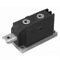
VSKT250-14
Description
SCR DBL HISCR 1400V 230A MAGNPAK
Manufacturer
Vishay
Specifications of VSKT250-14
Structure
Series Connection - All SCRs
Number Of Scrs, Diodes
2 SCRs
Voltage - Off State
1400V
Current - Gate Trigger (igt) (max)
200mA
Current - On State (it (av)) (max)
250A
Current - On State (it (rms)) (max)
555A
Current - Non Rep. Surge 50, 60hz (itsm)
8500A, 8900A
Current - Hold (ih) (max)
500mA
Mounting Type
Chassis Mount
Package / Case
3-MAGN-A-PAK™
Rated Repetitive Off-state Voltage Vdrm
1400 V
Off-state Leakage Current @ Vdrm Idrm
50 mA
Holding Current (ih Max)
500 mA
Mounting Style
Screw
Breakover Current Ibo Max
8900 A
Gate Trigger Current (igt)
200 mA
Gate Trigger Voltage (vgt)
3 V
Repetitive Peak Forward Blocking Voltage
1400 V
Lead Free Status / RoHS Status
Contains lead / RoHS non-compliant
Other names
*IRKT250-14
IRKT250-14
IRKT250-14
IRKT250-14
IRKT250-14


VSK.250, VSK.270, VSK.320 Series
Vishay Semiconductors
www.vishay.com
8
Fig. 19 - Maximum Non-Repetitive Surge Current
Fig. 20 - Maximum Non-Repetitive Surge Current
10000
Fig. 21 - Forward Voltage Drop Characteristics
8000
7000
6000
5000
4000
3000
2000
9000
8000
7000
6000
5000
4000
3000
2000
1000
100
10
Numb er Of Equal Amplitude Half Cyc le Current Pulses (N)
0.01
0.5
1
Ma ximum Non Rep etitive Surge Current
Instantaneous Forward Voltage (V)
VSK.270.. S eries
Per Junc tion
VSK.270.. S eries
Per Junction
At Any Ra ted Load Cond ition And With
Ra ted V
1
T = 25°C
J
Pulse T rain Dura tion (s)
1.5
Versus Pulse T rain Dura tion.
RR M
DiodesAmericas@vishay.com, DiodesAsia@vishay.com,
Rated V
No Voltage Reap plied
2
Ap plied Following Surge.
For technical questions within your region, please contact one of the following:
0.1
10
VSK.270.. S eries
Per Junc tion
2.5
Initia l T = 150°C
Initial T = 150°C
@ 60 Hz 0.0083 s
@ 50 Hz 0.0100 s
R RM
T = 150°C
3
Rea p plied
J
J
J
Standard Recovery Diodes, 250 A to 320 A
3.5
100
1
4
(MAGN-A-PAK Power Modules)
Fig. 22 - Thermal Impedance Z
0.001
DiodesEurope@vishay.com
0.01
150
140
130
120
110
100
150
140
130
120
110
100
0.1
90
80
90
80
0.001
Fig. 23 - Current Ratings Characteristics
Fig. 24 - Current Ratings Characteristics
1
0
0
S teady S tate Value:
R
(DC Operation)
thJC
S quare Wave Pulse Duration (s)
50
100
Average F orward Current (A)
Average Forward Current (A)
0.01
= 0.45 K/ W
30°
100
60°
200
0.1
90°
30°
VSK.320.. S eries
R
VSK.320.. S eries
R
150
thJC
120°
thJC
300
200
VSK.270.. S eries
Per Junction
(DC) = 0.125 K/ W
(DC) = 0.125 K/ W
60°
180°
Conduction Angle
Conduc tion Period
1
400
thJC
90°
Document Number: 93581
250
DC
Characteristics
120°
10
500
300
180°
Revision: 02-Jul-10
100
350
600
Related parts for VSKT250-14
Image
Part Number
Description
Manufacturer
Datasheet
Request
R

Part Number:
Description:
SCR DBL HISCR 400V 230A MAGNAPAK
Manufacturer:
Vishay
Datasheet:
Part Number:
Description:
SCR DBL HISCR 800V 230A MAGNAPAK
Manufacturer:
Vishay
Datasheet:
Part Number:
Description:
SCR DBL HISCR 1200V 230A MAGNPAK
Manufacturer:
Vishay
Datasheet:

Part Number:
Description:
SCR Modules 250 Amp 1600 Volt 550 Amp IT(RMS)
Manufacturer:
Vishay
Datasheet:
Part Number:
Description:
SCR THYRISTOR, 250A 1.6KV ADD-A-PAK
Manufacturer:
Vishay
Datasheet:

Part Number:
Description:
STANDARD RECOVERY DIODES, 250 TO 320 A (MAGN-A-PAK POWER MODULES)
Manufacturer:
Vishay
Part Number:
Description:
SCR Modules 250 Amp 1400 Volt 550 Amp IT(RMS)
Manufacturer:
Vishay
Part Number:
Description:
SCR Modules 250 Amp 800 Volt 550 Amp IT(RMS)
Manufacturer:
Vishay
Datasheet:
Part Number:
Description:
SCR Modules 250 Amp 400 Volt 550 Amp IT(RMS)
Manufacturer:
Vishay
Part Number:
Description:
357-036-542-201 CARDEDGE 36POS DL .156 BLK LOPRO
Manufacturer:
Vishay
Datasheet:
Part Number:
Description:
357-036-542-201 CARDEDGE 36POS DL .156 BLK LOPRO
Manufacturer:
Vishay
Datasheet:
Part Number:
Description:
357-036-542-201 CARDEDGE 36POS DL .156 BLK LOPRO
Manufacturer:
Vishay
Datasheet:
Part Number:
Description:
357-036-542-201 CARDEDGE 36POS DL .156 BLK LOPRO
Manufacturer:
Vishay
Datasheet:
Part Number:
Description:
357-036-542-201 CARDEDGE 36POS DL .156 BLK LOPRO
Manufacturer:
Vishay
Datasheet: