VSKT430-18 Vishay, VSKT430-18 Datasheet
VSKT430-18
Specifications of VSKT430-18
IRKT430-18
IRKT430-18


Related parts for VSKT430-18


VSKT430-18 Summary of contents
Page 1
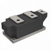
THYRISTOR / DIODE and THYRISTOR / THYRISTOR Features High current capability 3000 V isolating voltage with non-toxic substrate RMS High surge capability High voltage ratings up to 2000V Industrial standard package UL recognition pending Typical Applications Motor starters DC motor ...
Page 2
IRK.430.. Series Bulletin I27400 rev. A 09/97 ELECTRICAL SPECIFICATIONS Voltage Ratings Voltage V /V RRM DRM Type number Code peak reverse voltage 16 IRK.430 On-state Conduction Parameter I Maximum average on-state current T(AV Case temperature F(AV) ...
Page 3
Blocking Parameter dv/dt Maximum critical rate of rise of off-state voltage V RMS isolation voltage INS I Maximum peak reverse and off-state RRM I leakage current DRM Triggering Parameter P Maximum peak gate power GM P Maximum peak average gate ...
Page 4
IRK.430.. Series Bulletin I27400 rev. A 09/97 R Conduction thJC (The following table shows the increment of thermal resistance R Conduction angle Sinusoidal conduction Rectangular conduction 180° 0.009 120° 0.011 90° 0.014 60° 0.021 30° 0.037 Ordering Information Table Device ...
Page 5
Outline Table All dimensions in millimeters (inches) 130 IRK.430.. Series R (DC) = 0.065 K/W thJC 120 110 Conduction Angle 100 90 60° 30° 90° 80 120° 100 200 300 Average On-state Current (A) Fig Current ...
Page 6
IRK.430.. Series Bulletin I27400 rev. A 09/97 700 180° 120° 600 90° 60° 500 30° 400 RMS Limit 300 Conduction Angle 200 IRK.430.. Series Per Junction 100 T = 130° 100 200 300 Average On-state Current (A) ...
Page 7
IRK.430.. Series Single Phase Bridge 500 0 0 100 200 300 400 500 600 700 800 900 Total Output Current (A) Fig On-state Power Loss Characteristics 5000 4500 4000 3500 ...
Page 8
IRK.430.. Series Bulletin I27400 rev. A 09/97 100 Rectangular gate pulse a) Recommended load line for rated di/dt : 20V, 10ohms; tr<=1 µs b) Recommended load line for <=30% rated di/dt : 10V, 10ohms 10 tr<=1 µs 1 VGD IGD ...