EE-SX1088-W1 Omron, EE-SX1088-W1 Datasheet
EE-SX1088-W1
Manufacturer Part Number
EE-SX1088-W1
Description
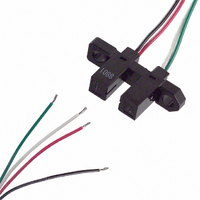
OPTO SENSOR VERT SLOT 3.4MM
Manufacturer
Omron
Type
Unamplifiedr
Datasheet
1.EE-SX1088-W1.pdf
(2 pages)
Specifications of EE-SX1088-W1
Sensing Distance
0.134" (3.4mm)
Sensing Method
Transmissive
Output Configuration
Phototransistor
Current - Dc Forward (if)
50mA
Current - Collector (ic) (max)
20mA
Voltage - Collector Emitter Breakdown (max)
30V
Response Time
4µs, 4µs
Mounting Type
Chassis Mount
Package / Case
Module, Pre-Wired
Operating Temperature
-25°C ~ 85°C
Aperture Orientation
Horizontal
Aperture Width
0.5 mm
Termination Style
Wire
No. Of Channels
1
Optocoupler Output Type
Phototransistor
Input Current
30mA
Output Voltage
30V
Opto Case Style
Through Hole
No. Of Pins
4
Operating Temperature Range
-25°C To +85°C
External Depth
6mm
External Width
25mm
Rohs Compliant
Yes
Lead Free Status / RoHS Status
Lead free / RoHS Compliant
Lead Free Status / RoHS Status
Lead free / RoHS Compliant, Lead free / RoHS Compliant
Other names
EESX1088W1
OR562
OR562


■ Dimensions
Note: All units are in millimeters unless otherwise indicated.
■ Electrical and Optical Characteristics (Ta = 25 C)
52
Emitter
Detector
Rising time
Falling time
A
K
C
E
K
A
Terminal No.
Photomicrosensor (Transmissive)
EE-SX1088
8.4 0.1
3 0.4
Cross section BB
Internal Circuit
Two, 3.2 0.2 dia. holes
Be sure to read Precautions on page 25.
0.5 0.1
Two, R1
EE-SX1088
Four, 0.25
Forward voltage
Reverse current
Peak emission wavelength
Light current
Dark current
Leakage current
Collector–Emitter saturated volt-
age
Peak spectral sensitivity wave-
length
Anode
Cathode
Collector
Emitter
Name
Item
C
E
19 0.15
25 0.2
Unless otherwise specified, the
tolerances are as shown below.
Four, C0.3
3 mm max.
3
6
10
18
Dimensions
Photomicrosensor (Transmissive)
mm
mm
(Optical axis)
mm
mm
5 0.2 6 0.2
2.5 0.1
6
10
Two, C2
18
30
7.2 0.2
10 0.2
Four, 0.5
V
I
I
I
I
V
tr
tf
Tolerance
R
L
D
LEAK
P
P
F
CE
0.3
0.375
0.45
0.55
0.65
Cross section AA
Symbol
(sat)
0.5 0.1
6.5 0.1
1.2 V typ., 1.5 V max.
0.01 A typ., 10 A max.
940 nm typ.
0.5 mA min., 14 mA max.
2 nA typ., 200 nA max.
---
0.15 V typ., 0.4 V max.
850 nm typ.
4 s typ.
4 s typ.
■ Features
• General-purpose model with a 3.4-mm-wide slot.
• Mounts to PCBs or connects to connectors.
• High resolution with a 0.5-mm-wide aperture.
• OMRON’s XK8-series Connectors can be connected without sol-
■ Absolute Maximum Ratings (Ta = 25 C)
Note: 1. Refer to the temperature rating chart if the ambient temper-
dering. Contact your OMRON representative for information on
obtaining XK8-series Connectors.
Emitter
Detector
Ambient tem-
perature
Soldering temperature
2. The pulse width is 10
3. Complete soldering within 10 seconds.
ature exceeds 25 C.
100 Hz.
Value
Item
Forward current
Pulse forward cur-
rent
Reverse voltage
Collector–Emitter
voltage
Emitter–Collector
voltage
Collector current
Collector dissipa-
tion
Operating
Storage
I
V
I
I
V
---
I
V
V
V
F
F
F
F
R
CE
CE
CC
CC
= 30 mA
= 20 mA
= 20 mA, V
= 20 mA, I
s maximum with a frequency of
= 4 V
= 10 V, 0 lx
= 10 V
= 5 V, R
= 5 V, R
I
I
V
V
V
I
P
Topr
Tstg
Tsol
F
FP
C
Symbol
R
CEO
ECO
C
L
L
L
Condition
CE
= 0.1 mA
= 100
= 100
= 10 V
50 mA
(see note 1)
1 A
(see note 2)
4 V
30 V
---
20 mA
100 mW
(see note 1)
–25 C to 85 C
–30 C to
100 C
260 C
(see note 3)
, I
, I
Rated value
L
L
= 5 mA
= 5 mA
Related parts for EE-SX1088-W1
Image
Part Number
Description
Manufacturer
Datasheet
Request
R

Part Number:
Description:
G6S-2GLow Signal Relay
Manufacturer:
Omron Corporation
Datasheet:
Part Number:
Description:
Compact, Low-cost, SSR Switching 5 to 20 A
Manufacturer:
Omron Corporation
Datasheet:
Part Number:
Description:
Manufacturer:
Omron Corporation
Datasheet:
Part Number:
Description:
Manufacturer:
Omron Corporation
Datasheet:
Part Number:
Description:
Manufacturer:
Omron Corporation
Datasheet:
Part Number:
Description:
Manufacturer:
Omron Corporation
Datasheet:
Part Number:
Description:
Manufacturer:
Omron Corporation
Datasheet:
Part Number:
Description:
Manufacturer:
Omron Corporation
Datasheet:
EE-SX1088-W1 Summary of contents
Page 1
... Item Symbol I Forward current F I Pulse forward cur- FP rent V Reverse voltage R V Collector–Emitter CEO voltage V Emitter–Collector ECO voltage I Collector current C P Collector dissipa- C tion Topr Operating Tstg Storage Tsol ature exceeds maximum with a frequency of 100 Hz. Value Condition mA --- mA 0 ...
Page 2
... Engineering Data Forward Current vs. Collector Dissipation Temperature Rating Ambient temperature Light Current vs. Collector Emitter Voltage Characteristics (Typical Collector Emitter voltage V (V) CE Response Time vs. Load Resist- ance Characteristics (Typical Load resistance Response Time Measurement Circuit Input 90 % Output 10 % Input Output Forward Current vs. Forward ...