115140126 C&K Components, 115140126 Datasheet - Page 4
115140126
Manufacturer Part Number
115140126
Description
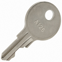
KEY REPLACEMENT A126 CODE BRASS
Manufacturer
C&K Components
Type
Keyr
Datasheet
1.115140126.pdf
(5 pages)
Specifications of 115140126
Accessory Type
Key Replacement
Switch Type
Key Lock Switch
Lead Free Status / RoHS Status
Lead free / RoHS Compliant
For Use With/related Products
Y Series, 4 Tumbler
For Use With
CKC8026 - SWITCH KEYLOC SP3T 4A 6"WIRES 4PCKC8046 - SWITCHLOCK DP 4A SOLDER LUGCKC8045 - SWITCHLOCK DP 4A SOLDER/NOTCHCKC8044 - SWITCHLOCK DP 4A SOLDER LUGCKC8043 - SWITCHLOCK DP 4A SOLDER LUGCKC8042 - SWITCHLOCK SPDT 4A SOLDER LUGCKC8039 - SWITCHLOCK SPDT 4A SOLDER LUGCKC8038 - SWITCHLOCK SPDT 4A SOLDER/NOTCHCKC8037 - SWITCHLOCK SP4T 4A SOLDER LUGCKC8036 - SWITCHLOCK SP3T 4A SOLDER LUGCKC1231 - SWITCHLOCK DPDT SLD LUG HOLE 4ACKC1230 - SWITCHLOCK SPDT SOLDER LUG 4ACKC8001 - SWITCHLOCK DP SLD 4A 4PCSCKC8000 - SWITCHLOCK SPDT SOLDER 4A 4PCSCKC8003 - SWITCHLOCK DP PC 4A 4PCSCKC8002 - SWITCHLOCK SPDT PC MNT 4A
Lead Free Status / Rohs Status
Lead free / RoHS Compliant
Other names
*115140126
115140126
CKC8028
115140126
CKC8028


L
H Series
4 & 6 Tumbler Power Switchlocks
1
2
Nut part number: 175050700
N
CONTACTS & TERMINALS: Copper, with gold plate over nickel plate.
CONTACTS & TERMINALS: Copper, silver plated.
OPTION
CODE
Q
B
WITH NUT
COMPLIANT *
RoHS
YES
YES
COMPATIBLE *
0.468 +.062
RoHS
MOUNTING/LOCK STYLE
YES
YES
-.000
CONTACT MATERIAL
0.225
± 0.010
Clip part number: 906B00000
D
TERMINAL MATERIAL
CONTACT AND
WITH CLIP
0.034
90
0.100
SILVER
GOLD
0
0.062
Switch and Lock Assembly Instructions
0.062
0.688
1
2
0.965
± 0.010
R 0.688
0.085
* Note: See Technical Data section of this catalog for RoHS compliant and compatible
definition and specifications.
All models
1. Place lock assembly in mounting hole on panel,
2. Align keying tab on switch assembly with keying slot
3. Snap assemblies together.
4. Switch installation is permanent. Switch cannot be
LOW LEVEL/DRY CIRCUIT
0.563
0.327
0.500
secure with mounting nut.
on lock assembly.
removed from lock after assembly. Attempting to separate
switch and lock may cause damage to switchlock.
L–42
± .003
R 0.048
POWER
0.235
1.000
o
± .010
with all options when ordered with ‘Q’ contact material.
0.470
Ø 0.136
R 0.030 ± .010
0.657
0.652
BURR SIDE UP
GRAIN
DIRECTION
R 0.375
12 AMPS @ 125 V AC; 6 AMPS @ 250 V AC;
1 AMP @ 125 V DC (UL/CSA).
0.105
0.4 VA MAX. @ 20 V AC or DC MAX.
± .010
RATING
Specifications and dimensions subject to change
MOUNTING
STYLES
D
N
www.ck-components.com
PANEL MOUNTING
Dimensions are shown: Inch (mm)
.065-.085 (1,65-2,16)
PANEL THICKNESS
.195 (4,95) max.
Related parts for 115140126
Image
Part Number
Description
Manufacturer
Datasheet
Request
R

Part Number:
Description:
Switch Hardware PUSHBUTTON SWITCH
Manufacturer:
C&K Components
Datasheet:

Part Number:
Description:
Rotary Switches 4P 3 POS ROTARY SW
Manufacturer:
C&K Components
Part Number:
Description:
ANALOG ROCKER C&K DELTATECH
Manufacturer:
C&K Components
Part Number:
Description:
QUARDANT MODUL C&K DELTATECH
Manufacturer:
C&K Components
Datasheet:
Part Number:
Description:
TOGGLE,THT-PC,SPDT,ON-OFF-ON,ACT-DXL:6.09X17.15MM,BUSH-THREADED,AU
Manufacturer:
C&K Components
Part Number:
Description:
SMARTCARD CONNECTOR *Y1112-2013AP LFT
Manufacturer:
C&K Components
Part Number:
Description:
Connector reel; SIM card; 6 contacts; hinged; no switch lock
Manufacturer:
C&K Components