A22-24AY Omron, A22-24AY Datasheet - Page 20
A22-24AY
Manufacturer Part Number
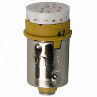
A22-24AY
Description
LAMP A22 SERIES 24VAC/DC LED YLW
Manufacturer
Omron
Type
LED, 10.6 mm Diameterr
Series
A22r
Specifications of A22-24AY
Accessory Type
LED Lamp Replacement
Color
Yellow
Illumination
Illuminated
Contact Rating
8 mAmps at 24 VoltsAC/DC
Height
20 mm
Illumination Color
Yellow
Mounting Style
Snap In
Termination Style
Socket
For Use With/related Products
A22 Series
For Use With
Z1496 - SWITCH PB RND MOM SPST-NO ILLZ1495 - SWITCH PB ILL RND MOM SPST-NOZ1492 - SWITCH PB RND MOM SPST-NC ILLZ1494 - SWITCH PB ILL RND MOM SPST-NOZ1486 - SWITCH PB ILL RND MOM SPST-NOZ1485 - SWITCH PB ILL RND MOM SPST-NOZ1482 - SWITCH PB RND MOM SPST-NC ILLZ1484 - SWITCH PB ILL RND MOM SPST-NOZ1483 - SWITCH PB RND MOM SPST-NO ILLZ1477 - SWITCH PB SQ MOM SPST-NO ILL-YLWZ1476 - SWITCH PB SQ MOM SPST-NO ILL-WHTZ1475 - SWITCH PB SQ MOM SPST-NO ILL-GRNZ1474 - SWITCH PB SQ MOM SPST-NO ILL-BLU
Lead Free Status / RoHS Status
Lead free / RoHS Compliant
Lead Free Status / RoHS Status
Lead free / RoHS Compliant, Lead free / RoHS Compliant
Other names
A2224AY
Z1578
Z1578


Technical Information
•
•
•
•
18
Hand soldering
Automatic
soldering
Do not use soldering flux that contains chlorine. Doing so may
result in metal corrosion.
Perform hand soldering using the appropriate soldering iron.
With the exception of PCB-mounting Switches, when performing
hand soldering, hold the Switch so that the terminals point
downwards so that flux does not get inside the Switch.
Leave a gap of at least 1 mm between the soldered parts and the
surface of the case so that flux does not get inside the Switch.
Correct
Terminal
Method
Incorrect
Dip
soldering
Reflow
soldering
Incorrect
Lead wire
Perform soldering for be-
tween 3 to 5 s with a suit-
able soldering iron.
Large-
capacity
soldering
iron
Soldering iron
Jet soldering
bath
Dip soldering
bath
Infrared reflow
(IR) soldering
bath
Vapor-phase
(VPS) reflow
soldering bath
Soldering
device
Incorrect
Correct
Small-capacity
soldering iron
used for a long
time
Small quantities
Different
materials
Lead wire
terminals
Large quantities
of discrete
terminals
Large quantities
of miniature
SMD terminals
Application
•
•
When applying flux using a brush, use a sponge soaked in flux as
shown below. Do not apply more than is necessary. Also, apply
the flux with the PCB inclined at an angle of less than 80° so that
flux does not flow onto the mounting surface of the Switch.
Do not place PCBs that have had flux applied or have been
soldered on top of each other. Otherwise, the flux on the PCB’s
solder surface may stain the upper part of the Switch or even
permeate the inside of the Switch and cause contact failure.
Incorrect
Flux
Incorrect
Correct
Sponge
soaked in flux
Flux
Lead wire
Terminal
Case
Solder
Brush
Brush
Technical Information
Do not place PCBs
with solder or flux on
top of each other.
80°C
max.
1 mm min.
Related parts for A22-24AY
Image
Part Number
Description
Manufacturer
Datasheet
Request
R

Part Number:
Description:
SWITCH PB ILLUM RND MOM SPST BLU
Manufacturer:
Omron
Datasheet:
Part Number:
Description:
SWITCH PB ILLUM RND MOM SPST BLU
Manufacturer:
Omron
Datasheet:
Part Number:
Description:
SWITCH PB ILLUM RND MOM SPST GRN
Manufacturer:
Omron
Datasheet:
Part Number:
Description:
SWITCH PB ILLUM RND MOM SPST GRN
Manufacturer:
Omron
Datasheet:
Part Number:
Description:
SWITCH PB ILLUM RND MOM SPST RED
Manufacturer:
Omron
Datasheet:
Part Number:
Description:
SWITCH PB ILLUM RND MOM SPST RED
Manufacturer:
Omron
Datasheet:
Part Number:
Description:
SWITCH PB ILLUM RND MOM SPST WHT
Manufacturer:
Omron
Datasheet:
Part Number:
Description:
SWITCH PB ILLUM RND MOM SPST WHT
Manufacturer:
Omron
Datasheet:
Part Number:
Description:
SWITCH PB ILLUM RND MOM SPST YEL
Manufacturer:
Omron
Datasheet:
Part Number:
Description:
SWITCH PB ILLUM RND MOM SPST YEL
Manufacturer:
Omron
Datasheet:
Part Number:
Description:
SWITCH PB ILLUM RND MOM DPST BLU
Manufacturer:
Omron
Datasheet:
Part Number:
Description:
SWITCH PB ILLUM RND MOM SPST BLU
Manufacturer:
Omron
Datasheet:
Part Number:
Description:
SWITCH PB ILLUM RND MOM DPST BLU
Manufacturer:
Omron
Datasheet:
Part Number:
Description:
SWITCH PB ILLUM RND MOM DPST GRN
Manufacturer:
Omron
Datasheet:
Part Number:
Description:
SWITCH PB ILLUM RND MOM SPST GRN
Manufacturer:
Omron
Datasheet: