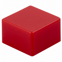
B32-1280 Omron, B32-1280 Datasheet

B32-1280
Specifications of B32-1280
SW256
Related parts for B32-1280
B32-1280 Summary of contents
Page 1
... B3FS-1000 models (Flat type) 4.3 mm (Flat type) 7.3 mm (Projected type) Note: Orders must be made in multiples of the minimum order unit. Switches are not sold individually. Height Operating force (OF) Model 0.98 N {100 gf} B3FS-1000 1.47 N {150 gf} B3FS-1002 0.98 N {100 gf} B3FS-1010 1.47 N {150 gf} B3FS-1012 ...
Page 2
B3FS Specifications Ratings/Characteristics ■ Switching capacity 50 mA, 24 VDC (resistive load) Operating: –25 ° ° C (with no icing) Ambient temperature Ambient humidity Operating: 35% to 85% Contact configuration SPST-NO 100 m W max. (initial value) ...
Page 3
... Key Tops B32-series Special Key Tops are available for projected plunger models. Refer to page 42 for details. Precautions Be sure to read the precautions common to all Tactile Switches on pages for correct use. ALL DIMENSIONS SHOWN ARE IN MILLIMETERS. To convert millimeters into inches, multiply by 0.03937. To convert grams into ounces, multiply by 0.03527. ...
Page 4
... B32-1200 B32-2010 B32-2110 B32-1210 --- --- B32-1220 --- --- B32-1230 --- --- B32-1240 --- --- B32-1260 --- --- B32-1280 –25 ° ° 60% max. humidity (with no icing or condensation) 35% to 85% ( ° C) B32 12 × Switches (B3F-4000, B3F-5000, B3W-4000) 9 × × 9.5-mm dia. Key Top Key Top B32-1300 B32-1600 B32-1310 B32-1610 B32-1320 B32-1620 B32-1330 B32-1630 ...
Page 5
... B32-10@0 R0.2 5.5 1.6 R0.5 4 2.5 ±0.15 2.3 2.5 4 ±0.15 B32-2000 B32-2010 R0.2 5.5 ±0.1 6 ±0.1 dia. 1.8 2.5 B32-2100 B32-2110 R0.2 5.5 ±0.1 6 ±0.1 2.7 6 ±0.1 1.8 2.5 B32-12@0 5.5 9 ±0.15 3.8 ±0.1 9 ±0.15 Reference Dimensions 2 2.8 1.0 to 2.0 10.0 ± ...
Page 6
... To convert millimeters into inches, multiply by 0.03937. To convert grams into ounces, multiply by 0.03527. Cat. No. A077-E1-04 44 Reference Dimensions R0.2 2.8 10.0 ±0.4 R0.5 3.8 ±0.1 Reference Dimensions 2.8 9.5 dia. ±0.2 11.5 ±0.4 3.8 ±0.1 B32 Panel Cutout 1.0 to 2.0 +0.05 12.2 0 Panel +0.05 12 board Panel Cutout 1.0 to 2.0 +0.05 9.7 dia. 0 Panel PC board ...
Page 7
... Confirm the conditions beforehand. Do not use an automatic soldering bath for surface-mounted Resin sheet Switches. The soldering gas or flux may enter the Switch and damage the Switch’s push-button operation. 4. Manual Soldering (All Models) Soldering temperature: 350 ° C max. at the tip of the soldering iron Soldering time max ...
Page 8
... Switch through respira- tion as the Switch cools. Wait for at least three minutes after sol- dering before cleaning washable models. Do not use Sealed Switches while submersed in water or in loca- tions exposed to water. Switch Packaging (Taping Specification Models) 1 ...
Page 9
... Make sure that the polarity of the LEDs is correct. The polarity is not indicated on the Switch, but the positive pole is located on the back surface of the Switch on the side without the OMRON mark. Connect limiting resistors to the LEDs. The Switch does not have built-in limiting resistors, so satisfy the LED characteristics by obtaining the limiting resistance according to the following formula based on the voltage to be used ...


