90HBW04PT Grayhill Inc, 90HBW04PT Datasheet - Page 2
90HBW04PT
Manufacturer Part Number
90HBW04PT
Description
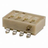
SWITCH 4 POS DIP GULL SEALED SMD
Manufacturer
Grayhill Inc
Series
90HBr
Specifications of 90HBW04PT
Circuit
SPST
Number Of Positions
4
Contact Rating @ Voltage
0.15A @ 30VDC
Actuator Type
Standard
Actuator Level
Flush
Mounting Type
Surface Mount
Orientation
Top Actuated
Washable
Yes
Contact Configuration
SPCO
No. Of Switch Positions
4
Actuator Style
Ball
Pitch Spacing
2.54mm
Contact Current Dc Max
100mA
Length/height, External
4.19mm
Peak Reflow Compatible (260 C)
Yes
Circuitry
SPST-CO
Switch Terminals
SMD Gull Wing
Rohs Compliant
Yes
External Width
7.37mm
Leaded Process Compatible
Yes
Switch Mounting
PCB
Lead Free Status / RoHS Status
Lead free / RoHS Compliant
Other names
GH7238
Available stocks
Company
Part Number
Manufacturer
Quantity
Price
Company:

Part Number:
90HBW04PT
Manufacturer:
GHY
Quantity:
4 094
Company:
Part Number:
90HBW04PT
Manufacturer:
GRAYHILL
Quantity:
2 000


Grayhill, Inc. • 561 Hillgrove Avenue • LaGrange, Illinois 60525-5997 • USA • Phone: 708-354-1040 • Fax: 708-354-2820 • www.grayhill.com
ORDERING INFORMATION
SPECIFICATIONS
Electrical Ratings
Make-and-break Current Rating: 2,000
operations per switch position at these resistive
loads:10 mA, 30 Vdc; or 10 mA, 50 mVdc; 10
mA, 50 mVdc; or 25 mA, 24 Vdc; or 100 mA,6
Vdc.
Contact Resistance: (measured at 10 mA, 50
mVdc). Initial: 20 mohms maximum, After Life:
100 mohms maximum
Insulation Resistance: Minimum, at 100 Vdc
between adjacent closed contacts and also
across open switch contacts.
Initial (Mohms): 5,000, After Life (Mohms): 1,000
Dielectric Strength: Minimum voltage (AC RMS)
measured
contacts and also across open switch contacts.
lnitial: 500 volts, After Life: 500 volts
Current Carry Rating: 3A maximum rise of
20°C
Switch Capacitance: 2 pF at 1 megahertz
Mechanical Ratings
Where Grayhill performance is superior, the MIL
spec is listed in parentheses.
Mechanical Life: 2,000 operations per switch
position
Vibration Resistance: Per Method 204, Test
Condition B , 1mS opening (10 mS allowed)
Mechanical Shock: Per Method 213, Test
Condition A. 1mS opening (10 mS allowed)
Thermal Shock Resistance: Per specification;
no failures; passes contact resistance.
Terminal Strength: Per specification
Thermal Aging: 1,000 hours at 85°C; no failures.
Available from your local Grayhill Distributor.
For prices and discounts, contact a local Sales
Office, an authorized local Distributor or Grayhill.
90HBW02PRT
between
Positions
No. of
10
2
3
4
5
6
7
8
9
adjacent
Series
Terminal Style: W = Gull Wing, J = J-Bend
RoHS compliant
Packaging: R = Tape and reel packaging (750 switches/reel)
Seal: P = Polyimide Seal
Number of Positions: 02 through 10
Blank = No Seal
Length
Inches
1.070"
.270"
.370"
.470"
.570"
.670"
.770"
.870"
.970"
closed
Blank = Tube packaging (each tube is 19.5" long)
Environmental Ratings
Meets all requirements of MIL- S-83504.
Operating Temperature Range: -40°C to +
85°C
Storage Temperature Range: -40°C to + 85°C
Moisture Resistance: Per MIL-STD-202,
Method 106.
Soldering Information
Solderability: Per MIL-STD-202, Method 208
Soldering Heat Resistance: Per MIL-S-83504,
six second test.
Recommended Processing Temperature:
220°C–230°C (1 pass—260°C maximum)
Processing Position: Switch is to be processed
with all actuators in the closed (on) position as
shipped.
Fluxing: Per EIA RS-448-2 with flux touching
switch body.
Cleaning: Passes immersion test using water/
detergent. Acceptable solutions include 1-1-1
trichlorethane, freon, (TF, TE, or TMS), isopropyl
alcohol, detergent (140°F maximum). Terpene
acceptable for Series 90 only. Solutions which
are not recommended include acetone,
11,9 mm
14,5 mm
17,0 mm
19,6 mm
22,1 mm
24,6 mm
27,2 mm
Length
Metric
6,9 mm
9,4 mm
Per Tube
Number
60
47
37
31
26
23
20
18
16
Surface Mount DIP Switches
methylene chloride, freon TMC.
Materials and Finishes
Shorting Member (Ball): Brass, gold-plate
over nickel barrier.
Base Contacts: Copper alloy, gold-plate
over nickel barrier.
Terminals: Copper alloy, matte tin plated over
nickel barrier.
Non-Conductive Parts: Thermoplastic (UL94V-
O)
Tape and Reel Packaging
Tape Seal Integrity: Passes gross leak test
using 125°C flourinert for 20 seconds minimum.
Reference MIL-STD-202, Method 112
Tape Seal: Polyimide film
TAPE AND REEL PACKAGING
Each reel has a 15.750 inch (390 mm)
minimum leader and a 6.30 inch (160
mm) minimum trailer.
EIA 481-2 or EIA 481-3
Meets requirements of
PIN ONE LOCATION
DIRECTION
OF FEED
16mm
16mm
13 INCH
DIAMETER REEL
CONDUCTIVE
PLASTIC EMBOSSED
TAPE
24mm
TAPE
32 &
44mm
TAPE
D I P
6
Related parts for 90HBW04PT
Image
Part Number
Description
Manufacturer
Datasheet
Request
R

Part Number:
Description:
Encoder; 32pos; custom switching; sealed; continous rotation;
Manufacturer:
Grayhill Inc
Part Number:
Description:
50EPT90-01-1-04N-C SINGLE DECK ROTARY 0.5(12.7mm)DIA,200mA,Continuous
Manufacturer:
Grayhill Inc
Part Number:
Description:
Rotary Switch seal adj.stop 36� 1deck 1pol/deck 56BSD36-01PAJN -bulk
Manufacturer:
Grayhill Inc
Part Number:
Description:
Rotary Switch, Screwdriver slot shaft, shaft/panel seal, PC mount, 30°
Manufacturer:
Grayhill Inc
Part Number:
Description:
Encoder MODIFIED SPECIAL VERSION OF GRH'S 60A18-4-040C
Manufacturer:
Grayhill Inc
Part Number:
Description:
GRAYHILL,SERIES 71,ROTARY SWITCH,1/8 SHAFT,30DEGREE,DECK,1 POLE/DECK,12POSITION/POLE,NON-SHORTING,CONTINUOUS .
Manufacturer:
Grayhill Inc
Part Number:
Description:
Keypad Legend, INC, Standard Font, White On Black
Manufacturer:
Grayhill Inc

Part Number:
Description:
SWITCH DIP EXTENDED UNSEAL 4POS
Manufacturer:
Grayhill Inc
Datasheet:

Part Number:
Description:
SWITCH DIP EXT RCKR UNSEALD 4POS
Manufacturer:
Grayhill Inc
Datasheet:
Part Number:
Description:
SWITCH DIP EXTENDED SEALED 4POS
Manufacturer:
Grayhill Inc
Datasheet:

Part Number:
Description:
SWITCH DIP RECESSED SEALED 4POS
Manufacturer:
Grayhill Inc
Datasheet:

Part Number:
Description:
SWITCH DIP EXTENDED UNSEAL 8POS
Manufacturer:
Grayhill Inc
Datasheet: