90HBJ03PT Grayhill Inc, 90HBJ03PT Datasheet - Page 5
90HBJ03PT
Manufacturer Part Number
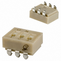
90HBJ03PT
Description
SWITCH DIP SEAL JLEAD SMD 3POS
Manufacturer
Grayhill Inc
Series
90HBr
Specifications of 90HBJ03PT
Circuit
SPST
Number Of Positions
3
Contact Rating @ Voltage
0.15A @ 30VDC
Actuator Type
Standard
Actuator Level
Flush
Mounting Type
Surface Mount
Orientation
Top Actuated
Washable
Yes
Contact Configuration
SPCO
No. Of Switch Positions
3
Actuator Style
Recessed Slide
Pitch Spacing
2.54mm
Contact Current Dc Max
100mA
Circuitry
SPST-CO
Contact Current Max
10mA
Lead Free Status / RoHS Status
Lead free / RoHS Compliant
Other names
GH7228


3.0 Subgroup 2:
4.0 Subgroup 3:
5.0 Subgroup 4:
Page 4 of 6
3.1. Moisture Resistance- Fifty switches were tested for moisture resistance as
specified in MIL- 202, Method 106, test condition B-1 (air).
3.2. Insulation Resistance. - After the moisture resistance test, the switches were tested
for insulation resistance per MIL-202, Method 302 with a requirement that the IR be
no less than 10 MegOhms.
3.3.Contact Resistance- Contact resistance measurements were taken after moisture
resistance and IR.
4.1. Resistance to IR Reflow Processing. -Fifty switches were run through three cycles
of a typical lead free reflow process using a thermal profile as shown. The test criteria
specify that there should be no evidence of physical or electrical damage to the
switches.
4.2 Contact Resistance- Contact resistance measurements taken after the reflow
processing must be less than 50 milliohms on all switch positions (10 mA @ 50mV
DC).
5.1. Resistance to IR Reflow Processing. - Twenty-five switches that were processed
in subgroup 3 for resistance to IR Reflow were used for the subgroup 4 testing.
5.2. Mechanical Shock- Twenty-five switches were tested as specified in MIL-202,
Method 213 using test condition “E” (1,000 G’s, 0.5mS, half sine) for the test. Each
switch was preset with half of the switches in the open position and half in the closed
position. With all switch positions monitored in accordance with Method 310 of MIL-
202, no opening or closing of contacts in excess of 10 microseconds is allowed during
the test period.
5.3. Resistance to Vibration- After mechanical shock, the twenty five switches were
tested as specified in MIL-202, Method 204 to test condition “B” (10-2000 Hz at 15G
or 0.06” double amplitude). Each switch was preset with half of the switches in the
open position and half in the closed position. No contact openings or closings in
excess of 10 microseconds are allowed during the test. The switches were then
inspected for any mechanical or physical damage.
5.4. Contact Resistance- Contact resistance measurements were taken after the Shock
and Vibration testing were completed. Contact resistance must be less than 50
milliohms at all switch positions after testing.
All fifty switches that were tested in this subgroup met the requirements as
specified.
All fifty switches that were tested met the requirements as specified.
All twenty-five switches tested met the requirements as specified.
561 Hillgrove Ave., LaGrange, Illinois 60525-5997 USA
Phone: 708-354-1040 Fax: 708-354-2820 http://www.grayhill.com
Related parts for 90HBJ03PT
Image
Part Number
Description
Manufacturer
Datasheet
Request
R

Part Number:
Description:
Encoder; 32pos; custom switching; sealed; continous rotation;
Manufacturer:
Grayhill Inc
Part Number:
Description:
50EPT90-01-1-04N-C SINGLE DECK ROTARY 0.5(12.7mm)DIA,200mA,Continuous
Manufacturer:
Grayhill Inc
Part Number:
Description:
Rotary Switch seal adj.stop 36� 1deck 1pol/deck 56BSD36-01PAJN -bulk
Manufacturer:
Grayhill Inc
Part Number:
Description:
Rotary Switch, Screwdriver slot shaft, shaft/panel seal, PC mount, 30°
Manufacturer:
Grayhill Inc
Part Number:
Description:
Encoder MODIFIED SPECIAL VERSION OF GRH'S 60A18-4-040C
Manufacturer:
Grayhill Inc
Part Number:
Description:
GRAYHILL,SERIES 71,ROTARY SWITCH,1/8 SHAFT,30DEGREE,DECK,1 POLE/DECK,12POSITION/POLE,NON-SHORTING,CONTINUOUS .
Manufacturer:
Grayhill Inc
Part Number:
Description:
Keypad Legend, INC, Standard Font, White On Black
Manufacturer:
Grayhill Inc

Part Number:
Description:
SWITCH DIP EXTENDED UNSEAL 4POS
Manufacturer:
Grayhill Inc
Datasheet:

Part Number:
Description:
SWITCH DIP EXT RCKR UNSEALD 4POS
Manufacturer:
Grayhill Inc
Datasheet:
Part Number:
Description:
SWITCH DIP EXTENDED SEALED 4POS
Manufacturer:
Grayhill Inc
Datasheet:

Part Number:
Description:
SWITCH DIP RECESSED SEALED 4POS
Manufacturer:
Grayhill Inc
Datasheet:

Part Number:
Description:
SWITCH 4 POS DIP GULL SEALED SMD
Manufacturer:
Grayhill Inc
Datasheet: