A22K-2AL-11 Omron, A22K-2AL-11 Datasheet - Page 20
A22K-2AL-11
Manufacturer Part Number
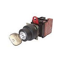
A22K-2AL-11
Description
SWITCH KEYLOC 2POS MOM SPST-NO/C
Manufacturer
Omron
Series
A22Kr
Specifications of A22K-2AL-11
Circuit
DPST (1-NO, 1-NC)
Number Of Positions
2
Contact Rating @ Voltage
10A @ 110VAC
Actuator Type
Flat Key
Mounting Type
Panel Mount
Termination Style
Screw Terminal
Key Removable Positions
Left
Angle Of Throw
90°
Contact Form
SPST - NO / NC
Switch Function
Alternate
Contact Rating
3 Amps
Lead Free Status / RoHS Status
Lead free / RoHS Compliant
Lead Free Status / RoHS Status
Lead free / RoHS Compliant, Lead free / RoHS Compliant
Other names
A22K2AL11


Technical Information
•
•
•
•
18
Hand soldering
Automatic
soldering
Do not use soldering flux that contains chlorine. Doing so may
result in metal corrosion.
Perform hand soldering using the appropriate soldering iron.
With the exception of PCB-mounting Switches, when performing
hand soldering, hold the Switch so that the terminals point
downwards so that flux does not get inside the Switch.
Leave a gap of at least 1 mm between the soldered parts and the
surface of the case so that flux does not get inside the Switch.
Correct
Terminal
Method
Incorrect
Dip
soldering
Reflow
soldering
Incorrect
Lead wire
Perform soldering for be-
tween 3 to 5 s with a suit-
able soldering iron.
Large-
capacity
soldering
iron
Soldering iron
Jet soldering
bath
Dip soldering
bath
Infrared reflow
(IR) soldering
bath
Vapor-phase
(VPS) reflow
soldering bath
Soldering
device
Incorrect
Correct
Small-capacity
soldering iron
used for a long
time
Small quantities
Different
materials
Lead wire
terminals
Large quantities
of discrete
terminals
Large quantities
of miniature
SMD terminals
Application
•
•
When applying flux using a brush, use a sponge soaked in flux as
shown below. Do not apply more than is necessary. Also, apply
the flux with the PCB inclined at an angle of less than 80° so that
flux does not flow onto the mounting surface of the Switch.
Do not place PCBs that have had flux applied or have been
soldered on top of each other. Otherwise, the flux on the PCB’s
solder surface may stain the upper part of the Switch or even
permeate the inside of the Switch and cause contact failure.
Incorrect
Flux
Incorrect
Correct
Sponge
soaked in flux
Flux
Lead wire
Terminal
Case
Solder
Brush
Brush
Technical Information
Do not place PCBs
with solder or flux on
top of each other.
80°C
max.
1 mm min.
Related parts for A22K-2AL-11
Image
Part Number
Description
Manufacturer
Datasheet
Request
R

Part Number:
Description:
REPLACEMENT KEY A22 SERIES 2 PCS
Manufacturer:
Omron
Datasheet:

Part Number:
Description:
Switch, Selector, 22mm, 10A, SPST-NO, 2 Position
Manufacturer:
Omron Automation
Datasheet:
Part Number:
Description:
Switch, Selector, 1NO-1NC CONTACT, 2 Position MAINTAINED, LEFT-RIGHT KEY RELEASE
Manufacturer:
Omron Automation
Datasheet:
Part Number:
Description:
Switch, Keylock, 2 Pos, DPST-NO
Manufacturer:
Omron Automation
Datasheet:

Part Number:
Description:
SWITCH KEY 2POS SPST-NO BLACK
Manufacturer:
Omron
Datasheet:

Part Number:
Description:
SWITCH KEYLOCK 2POS MOM SPST-NC
Manufacturer:
Omron
Datasheet:
Part Number:
Description:
SWITCH KEYLOCK 2POS ALT SPST-NC
Manufacturer:
Omron
Datasheet:
Part Number:
Description:
SWITCH KEYLOCK 2POS ALT SPST-NC
Manufacturer:
Omron
Datasheet:
Part Number:
Description:
SWITCH KEYLOCK 2POS MOM DPST-NC
Manufacturer:
Omron
Datasheet:
Part Number:
Description:
SWITCH KEYLOCK 2POS MOM DPST-NO
Manufacturer:
Omron
Datasheet:
Part Number:
Description:
SWITCH PB RND MOM SPST-NO/NC RED
Manufacturer:
Omron
Datasheet:

Part Number:
Description:
SWITCH PB ROUND ALT SPST-NO BLUE
Manufacturer:
Omron
Datasheet:

Part Number:
Description:
SWITCH PB ROUND ALT SPST-NO BLK
Manufacturer:
Omron
Datasheet:

Part Number:
Description:
SWITCH PB ROUND ALT SPST-NO GRN
Manufacturer:
Omron
Datasheet:

Part Number:
Description:
SWITCH PB ROUND ALT SPST-NO RED
Manufacturer:
Omron
Datasheet: