KB16MKW01 NKK Switches, KB16MKW01 Datasheet

SW PB SPDT ALT RND SILVER SLD MT

KB16MKW01

Manufacturer Part Number
KB16MKW01
Description
SW PB SPDT ALT RND SILVER SLD MT
Manufacturer
NKK Switches
Series
KBr
Type
Standardr
Datasheets

Specifications of KB16MKW01

Circuit
SPDT
Switch Function
On-On
Contact Rating @ Voltage
1A @ 125VAC
Actuator Type
Plunger for Cap
Mounting Type
Panel Mount, Snap-In
Termination Style
Solder Lug
Pole Throw Configuration
SPDT
Switch Configuration
ON ON
Actuator Style
Round Button
Current Rating (max)
1A
Ac Voltage Rating (max)
250VVAC
Dc Voltage Rating (max)
30VVDC
Contact Material
Copper
Contact Plating
Gold
Housing Material
Polyamide/Polyamide
Mechanical Life
100000
Product Height (mm)
38.5mm
Product Depth (mm)
14mm
Product Length (mm)
14mm
Operating Temp Range
-25C to 50C
Mounting Style
Panel
Terminal Type
Solder Lug
Contact Form
DPDT
Contact Rating
1 Amp at 125 Volts, 250 Volts
Actuator
Plunger, Long
Terminal Seal
Unsealed
Flammability Rating
UL 94 V-0
Dielectric Strength
1000 Volts
Features
Snap-action mechanism for long life
Insulation Resistance
1000 MOhms
Led Supply Voltage
125 Volts
Body Style
Miniature
Current, Rating
1 A
Electrical Life
50000 Operations (Min.)
Material, Contact
Silver
Material, Terminal
Polyester (Base), Phosphor Bronze with Silver Flash Plating (Common), Brass with Silver Flash Plating (End)
Mounting Hole Size
0.484 "
Number Of Poles
1
Number Of Positions
2
Operation
On-On
Resistance, Contact
50 Milliohms (Max.)
Resistance, Insulation
1000 Megohms (Min.) @ 500 VDC
Standards
Flammability, UL Recognized and CSA Certified
Temperature, Operating
-25 to +50 °C
Termination
Solder
Voltage, Rating
125/250 VAC
Lead Free Status / RoHS Status
Lead free / RoHS Compliant
Illumination Type, Color
-
Illumination Voltage (nominal)
-
Lead Free Status / Rohs Status
Compliant
D
General
Series KB
Electrical Capacity (Resistive Load)
Other Ratings
Materials & Finishes
Environmental Data
Installation
Standards & Certifications
D22
Operating Temperature Range:
Soldering Time & Temperature:
Nominal Operating Force:
Flammability Standards:
Cap Installation Force:
Insulation Resistance:
Stationary Contacts:
Power Level (silver):
Movable Contactor:
Common Terminals:
Contact Resistance:
Dielectric Strength:
Logic Level (gold):
Mounting Torque:
Lamp Terminals:
Mechanical Life:
Contact Timing:
Terminal Base:
End Terminals:
Housing Base:
Electrical Life:
Vibration:
Humidity:
Housing:
Shock:
Travel:
CSA:
UL:
Specifications
1A @ 125/250V AC or 1A @ 30V DC
0.4VA maximum @ 28V AC/DC maximum (Applicable Range 0.1mA ~ 0.1A @ 20mV ~ 28V)
Note: Find additional explanation of operating range in Supplement section.
50 milliohms maximum
1,000 megohms minimum @ 500V DC
For Silver: 1,000V AC minimum between contacts for 1 minute minimum &
1,500V AC minimum between contacts & case for 1 minute minimum;
For Gold: 750V AC minimum between contacts for 1 minute minimum &
1,500V AC minimum between contacts & case for 1 minute minimum
100,000 operations minimum
50,000 operations minimum for silver; 100,000 operations minimum for gold
Single pole 0.98 ~ 2.45N for maintained & 0.98 ~ 1.96N for momentary;
Double pole 1.47 ~ 3.43N for maintained & 1.47 ~ 2.94N for momentary
Nonshorting (break-before-make)
Pretravel .087” (2.2mm); Overtravel .031” (0.8mm); Total Travel .118” (3.0mm)
Polyamide (UL94V-0)
Silver for power circuit; copper with gold plating for logic level circuit
Polyamide (UL94V-0)
Polyester
Phosphor bronze with silver flash plating for power circuit;
Phosphor bronze with gold flash plating for logic level circuit
Brass with silver flash plating for power circuit;
Brass with gold flash plating for logic level circuit
Phosphor bronze with nickel flash plating
–25°C through +50°C (–13°F through +122°F) for Illuminated
–25°C through +70°C (–13°F through +158°F) for Nonilluminated
90 ~ 95% humidity for 96 hours @ 40°C (104°F)
10 ~ 55Hz with peak-to-peak amplitude of 1.5mm traversing the frequency range & returning
in 1 minute; 3 right angled directions for 2 hours
50G (490m/s
0.78Nm (6.9 lb
4.51N (1.0 lbf) maximum downward force on cap
Manual Soldering: See Profile A in Supplement section.
UL94V-0 housing & housing base
File No. E44145
Single & double pole models recognized at 1A @ 125/250V AC, 1A @ 30V DC, & 0.4VA @ 28V DC.
Add “/U” to end of part number to order UL mark on switch.
Add “/CUL” to end of part number to order cULus mark on switch.
File No. 023535_0_000
Single & double pole models recognized at 1A @ 125/250V AC, 1A @ 30V DC, & 0.4VA @ 28V DC.
Add “/C” to end of part number to order CSA mark on switch.
2
) acceleration (tested in 6 right angled directions, with 3 shocks in each direction)
www.nkk.com
in) maximum
Miniature Pushbuttons

Related parts for KB16MKW01

KB16MKW01 Summary of contents

Page 1

... Add “/U” to end of part number to order UL mark on switch. Add “/CUL” to end of part number to order cULus mark on switch. File No. 023535_0_000 Single & double pole models recognized 125/250V AC 30V DC, & 0.4VA @ 28V DC. Add “/C” to end of part number to order CSA mark on switch. www.nkk.com Miniature Pushbuttons ...

Page 2

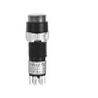
... Miniature Pushbuttons Distinctive Characteristics Bright illumination with numerous color variations. Spot illumination available. Square, rectangular, and round shaped caps. Front panel relamping. Choice of bright or super bright LEDs in red, amber, green, white, and blue. Latchdown feature gives indication of circuit status. Audible and tactile feedback with smooth and responsive operation. ...

Page 3

... JF & JG not suitable with neon. LED Cap: Lens/Diffuser Colors Resistor Square Spot Illuminated AB Black Cap/White Window No Code No Resistor Red JB Clear/White 05 5-volt Amber JC Clear/Red 12 12-volt JD Clear/Amber Green 24 24-volt JF Clear/Green LED Cap: Lens/Diffuser Colors White JB Clear/White Green Blue www.nkk.com Miniature Pushbuttons D D Green/White Green/Green Blue/White Blue/Blue D25 ...

Page 4

... Bezel or barrier is an integral part of the switch body. Panel Cutouts (4.9) With .193 Keyway (12.3) Dia .484 HOUSING www.nkk.com Miniature Pushbuttons Throw & Switch/Lamp Schematics Switch is marked with “+” and “–”. Lamp circuit is isolated and requires external power source. 2 (COM) L (+) (-) ...

Page 5

... Miniature Pushbuttons CONTACT MATERIALS, RATINGS & TERMINALS Power Level W Silver Contacts 1A @ 125V AC & 250V AC Logic Level G Gold Contacts 0.4VA maximum @ 28V AC/DC Complete explanation of operating range in Supplement section. A partitioned plastic guard is supplied with each switch to provide insulation between terminals. Installation steps: 1 ...

Page 6

... Material: Polycarbonate Finish: Glossy AT488 Round (11.6) Dia .457 (11.6) (4.5) (11.6) Sq .457 .177 .457 (4.5) (6.2) .177 .244 (6.2) .244 Material: Polycarbonate Finish: Glossy www.nkk.com Miniature Pushbuttons Green No Code No Resistor 5F Red Amber I 30mA 30mA FM I 20mA 20mA F V 1.9V 2. ∆ ...

Page 7

... Miniature Pushbuttons CAP TYPES & COLOR COMBINATIONS Color Codes: A Black B White Spot Illuminated Cap for Bright LED without Resistor or with Resistor Cap/Window Colors Available: Opaque Black Cap with Translucent White Window AB for Spot Illumination Cap for Bright LED without Resistor or LED with Resistor Lens/Diffuser Colors Available: (AT4133, 4132, 4134 white diffusers ...

Page 8

... Latchdown Position Single pole models do not have terminals 4, 5, & 6. www.nkk.com Miniature Pushbuttons (1.0) x (2.0) Typ (1.8) Keyway .039 x .079 .071 (0.2) Typ .008 (4. .193 5 2 COM ...

Page 9

... Miniature Pushbuttons (2.3) .090 (11.6) Sq (1.4) .457 .055 (14.0) Sq (3.5) (5.3) .551 .138 .209 Latchdown Position (2.3) .090 (11.6) Dia (1.4) .457 .055 (14.0) Dia (3.5) (5.3) .551 .138 .209 Latchdown Position (11.6) .457 (14.0) .551 (1.4) (16.1) .634 .055 (18.5) (3 ...

Page 10

... Single pole models do not have terminals 4, 5, & 6. Single & Double Pole (5.3) (16.1) .634 .209 (8.8) (24.7) (18.5) .728 .346 .972 Single pole models do not have terminals 4, 5, & 6. www.nkk.com Miniature Pushbuttons (1.0) x (2.0) Typ (1.8) Keyway .039 x .079 .071 (0.2) Typ .008 (4. .193 5 2 ...

Page 11

... Miniature Pushbuttons AT701 Single Pole Straight PC Terminals Switch (2.8) (0.3) Depth .110 .012 Keyway 6 (12.0) Dia + 5 COM .472 4 NO (0.6) Typ .024 (10.16) (9.8) (3.1) .400 .386 .122 (2.54) Typ .100 (2.54) Typ .100 COM NO 1 (0.8) Dia Typ .031 (10.16) ...

Page 12

... Marking Positive Lamp Socket Top View of Switch Negative Lamp Socket AT109 Cap Extractor www.nkk.com Miniature Pushbuttons Panel Thickness Range: .020” ~ .268” (0.5 ~ 6.8mm) (1.2) R for Bushing Mounting .047 .020” ~ .091” (9.0) (0.5 ~ 2.3mm) ...

Page 13

... Miniature Pushbuttons NKK Switches can provide custom legends for caps. Contact factory for more information. Recommended Methods: Screen Print or Pad Print on Lens. (10.08) Sq .397 (11.6) Sq .457 Lens Film Insert Filter or Diffuser (8.48) Sq Cap (10.0) Sq Base .394 LEGENDS Suggested Printable Area for KB Lens Epoxy based ink is recommended ...

Related keywords