LB15CKW01-6B-JB NKK Switches, LB15CKW01-6B-JB Datasheet - Page 4
LB15CKW01-6B-JB
Manufacturer Part Number
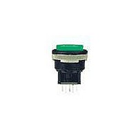
LB15CKW01-6B-JB
Description
SW PB ILLUM SPDT MOM RND WHT SLD
Manufacturer
NKK Switches
Series
LBr
Type
Illuminatedr
Datasheet
1.AT4171.pdf
(10 pages)
Specifications of LB15CKW01-6B-JB
Circuit
SPDT
Switch Function
On-Mom
Contact Rating @ Voltage
3A @ 125VAC
Actuator Type
Round Button
Illumination Type, Color
LED, White
Illumination Voltage (nominal)
3.6 VDC
Mounting Type
Panel Mount, Snap-In
Termination Style
Solder, Quick Connect - .110" (2.8mm)
Pole Throw Configuration
SPDT
Switch Configuration
ON ON
Actuator Style
Round Button
Current Rating (max)
3A
Illumination Type
Led
Ac Voltage Rating (max)
250VVAC
Dc Voltage Rating (max)
30VVDC
Contact Material
Silver Alloy
Contact Plating
Silver
Mechanical Life
1000000
Product Height (mm)
34mm
Product Depth (mm)
23.7mm
Product Length (mm)
23.7mm
Operating Temp Range
-25C to 50C
Mounting Style
Panel
Terminal Type
Quick Connect/Solder
Contact Form
SPDT
Contact Rating
3 Amps at 125 Volts, 250 Volts
Actuator
Button, Round
Supply Voltage
125 Volts, 250 Volts
Illumination
Illuminated
Illumination Color
White
Flammability Rating
UL 94 V-0
Body Length
21.5 mm
Body Shape
Round
Dielectric Strength
1000 Volts
Housing Material
Polyamide, Glass Fiber Reinforced
Insulation Resistance
200 MOhms
Led Size
T-1 Bi-pin
Mounting Angle
Vertical
Operating Force
4.41 N
Lead Free Status / RoHS Status
Lead free / RoHS Compliant


D
Series LB
D50
Pole
Cutout for 1 switch:
.638” x .638” (16.2mm x 16.2mm)
Cutout for 1 switch with barriers:
.638” x .815” (16.2mm x 20.7mm)
Housing Colors Available:
Complete explanation of operating range in Supplement section.
DP
SP
AT607 & AT607N
W01
S
G01
T-1 Bi-pin
.622” (15.8mm)
Square
*LB16
*LB26
Model
LB15
LB25
* When in latchdown position for the alternate circuit, cap position is .039” (1.0mm) above the built-in bezel.
Silver Contacts
Gold Contacts
Normal
( ) = Momentary
INCANDESCENT & NEON LAMP CODES & SPECIFICATIONS
Panel Thickness for Protective Guards & Splash Covers: .039” ~ .138” (1.0 ~ 3.5mm)
Plunger Position
ON
ON
ON
ON
(16.2) Sq
.638
AT607 Incandescent 5-volt or
12-volt; AT607N Neon 110-volt
Voltage
Current
Endurance
Ambient Temp. Range
Panel Thickness for Switches & Barriers: .039” ~ .157” (1.0 ~ 4.0mm)
Power Level
3A @ 125V AC & 250V AC
Logic Level
0.4VA max. @ 28V AC/DC max.
CONTACT MATERIALS, RATINGS & TERMINALS
Down
(ON)
(ON)
ON
ON
Avg.
C
Hours
SHAPES & PANEL CUTOUTS
1-3 4-6
Normal
Connected Terminals
K
1-3
V
.854” (21.7mm)
Round
I
POLES & CIRCUITS
www.nkk.com
115mA
5V AC
Black
05
HOUSING
.059
(1.5) R
–25°C ~ +50°C
10,000
1-2 4-5
Down
1-2
12V AC
60mA
12
Solder Lug/Quick Connect
Optional PCB adaptors
AT711 & AT712 available;
illustrated in “Optional
Accessories” immediately following
“Typical Switch Dimensions.”
(22.0) Dia
.866
Notes: Switch is marked with NC, NO, COM, L+, L–.
SPDT
DPDT
Standard Size Snap-in Pushbuttons
(11.5)
.453
110V AC
10,000
1.5mA
01
Lamp circuit is isolated and requires an
external power source.
Throw & Switch/Lamp Schematics
3
*
NC
1
R
G
COM
3
2
*
.622” x .866” (15.8mm x 22.0mm)
Rectangular
NC
NO
The electrical specifications shown are
determined at a basic temperature of
25°C. Lamp circuit is isolated and
requires external power source.
Recommended Resistors for Neon:
33K ohms for 110V AC;
100K ohms for 220V AC
1
Cutout for 1 switch:
.638” x .882” (16.2mm x 22.4mm)
Cutout for 1 switch with barriers:
.638” x 1.059” (16.2mm x 26.9mm)
Gray
COM
6
2
NO
NC
4
COM
5
Epoxy
Seal
NO
(2.0)
.079
L (+)
L (+)
(22.4)
.882
(2.8)
.110
.047
(1.2)
.295
(7.5)
Thk = (0.5)
(-) L
(-) L
.020
(16.2)
.638
Related parts for LB15CKW01-6B-JB
Image
Part Number
Description
Manufacturer
Datasheet
Request
R

Part Number:
Description:
SWITCH PB ILLUM SPDT MOM WHT
Manufacturer:
NKK Switches
Datasheet:

Part Number:
Description:
SW PB SPDT MOM RND SILV SLD MNT
Manufacturer:
NKK Switches
Datasheet:
Part Number:
Description:
SW PB SPDT MOM RND GRN CAP SLD
Manufacturer:
NKK Switches
Datasheet:
Part Number:
Description:
SW PB SPDT MOM RND RED CAP SLD
Manufacturer:
NKK Switches
Datasheet:
Part Number:
Description:
SW PB SPDT MOM RND BLK CAP SLD
Manufacturer:
NKK Switches
Datasheet:

Part Number:
Description:
SW PB SPDT MOM RND BK CAP SLD MT
Manufacturer:
NKK Switches
Datasheet:
Part Number:
Description:
SW PB SPDT MOM RND WHT CAP SLD
Manufacturer:
NKK Switches
Datasheet:
Part Number:
Description:
SW PB ILLUM SPDT MOM RND RED SLD
Manufacturer:
NKK Switches
Datasheet:
Part Number:
Description:
SW PB ILLUM SPDT MOM RND RED SLD
Manufacturer:
NKK Switches
Datasheet:
Part Number:
Description:
SW PB ILLUM SPDT MOM RND GRN SLD
Manufacturer:
NKK Switches
Datasheet:

Part Number:
Description:
SW PB ILLUM SPDT MOM RND RED SLD
Manufacturer:
NKK Switches
Datasheet:
Part Number:
Description:
SW PB ILLUM SPDT MOM RND BLU SLD
Manufacturer:
NKK Switches
Datasheet:
Part Number:
Description:
SW PB ILLUM SPDT MOM RND BLU SLD
Manufacturer:
NKK Switches
Datasheet:
Part Number:
Description:
SWITCH ILLUM PB SPDT RND 12V
Manufacturer:
NKK Switches
Datasheet:
Part Number:
Description:
SWITCH ILLUM PB SPDT RND 28V
Manufacturer:
NKK Switches
Datasheet: