A165W-A2MR-24D-2 Omron, A165W-A2MR-24D-2 Datasheet - Page 44
A165W-A2MR-24D-2
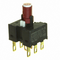
Manufacturer Part Number
A165W-A2MR-24D-2
Description
SWITCH KNOB SQUAR ILLUM 2POS RED
Manufacturer
Omron
Series
A165Wr
Type
Standardr
Specifications of A165W-A2MR-24D-2
Circuit
DPDT
Switch Function
2 Position, Maintained
Contact Rating @ Voltage
5A @ 125VAC
Illumination
Illuminated
Illumination Type, Color
LED, Red
Illumination Voltage (nominal)
24 VDC
Mounting Type
Panel Mount
Termination Style
Quick Connect - .110" (2.8mm)
Panel Cutout Dimensions
16mm (Round)
Body Shape
Flange
Control Type
Knob-Type Selector
Contact Form
DPDT
Contact Rating
24 VoltsDC
Flange Shape
Square
Illuminated
Y
Lens Color
Red
Lead Free Status / RoHS Status
Lead free / RoHS Compliant
Lead Free Status / RoHS Status
Lead free / RoHS Compliant, Lead free / RoHS Compliant
Other names
A165WA2MR24D2


Correct Use
J NUT MOUNTING
Insert the buzzer unit from the front of the panel and tighten the
mounting nut inserted from the rear of the panel.
Since a projection exists on the rear portion of the buzzer unit, if
the mounting nut cannot be fitted into position, turn the nut
slightly.
The tightening torque of the mounting nut should be less than
5 kg-cm.
Solder the terminals after mounting the nut. Otherwise, the
terminals, when thickened by solder, may prevent the nut from
being screwed down onto the buzzer unit.
J MOUNTING
Tighten the mounting nut at a torque of less than 5 kg-cm.
J WIRING
Exercise caution that the input terminals are not short-circuited
by the short-circuiting jumper.
Finish soldering within 5 seconds with a 30 watt soldering iron, or
within 3 seconds at a solder temperature of 240°C. For about a
minute after soldering, do not apply any force to the buzzer unit,
to avoid deforming the softened plastic buzzer unit base.
Use an non-corrosive, resin-based soldering flux.
J SNAP-IN MOUNTING
Attach the mounting leaf spring to the buzzer. Engage the edges
of the leaf spring in the two grooves on the threaded section of
the buzzer. After inserting the leaf spring edges into the grooves,
confirm that the leaf spring has seated. Be sure to attach both
leaf springs.
Insert the buzzer assembly into the hole on the mounting panel
from the front.
M2BJ-B
45
J SHORT-CIRCUITING JUMPER
The buzzer sounds continuously or intermittently depending on
how the short-circuiting bracket is attached to the case guide.
When the bracket is attached with the triangle on it facing
direction A (PC board side), the buzzer sounds intermittently.
To produce continuous sounds, attach the bracket to the case
guide so that the triangle on the bracket faces direction B.
M2BJ-B
Related parts for A165W-A2MR-24D-2
Image
Part Number
Description
Manufacturer
Datasheet
Request
R

Part Number:
Description:
SWITCH KNOB SQ 2-POS SPDT ILL
Manufacturer:
Omron
Datasheet:

Part Number:
Description:
SWITCH UNIT SQUARE ALT 2POS RED
Manufacturer:
Omron
Datasheet:

Part Number:
Description:
G6S-2GLow Signal Relay
Manufacturer:
Omron Corporation
Datasheet:
Part Number:
Description:
Compact, Low-cost, SSR Switching 5 to 20 A
Manufacturer:
Omron Corporation
Datasheet:
Part Number:
Description:
Manufacturer:
Omron Corporation
Datasheet:
Part Number:
Description:
Manufacturer:
Omron Corporation
Datasheet:
Part Number:
Description:
Manufacturer:
Omron Corporation
Datasheet:
Part Number:
Description:
Manufacturer:
Omron Corporation
Datasheet:
Part Number:
Description:
Manufacturer:
Omron Corporation
Datasheet:
Part Number:
Description:
Manufacturer:
Omron Corporation
Datasheet: