V-15G4-1C25-K Omron, V-15G4-1C25-K Datasheet - Page 9
V-15G4-1C25-K
Manufacturer Part Number
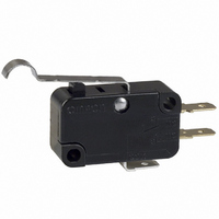
V-15G4-1C25-K
Description
SWITCH SIM ROLLER SPDT 15A
Manufacturer
Omron
Series
Vr
Type
Snap Actionr
Specifications of V-15G4-1C25-K
Circuit
SPDT
Switch Function
On-Mom
Contact Rating @ Voltage
15A @ 250VAC
Actuator Type
Lever, Simulated Roller
Mounting Type
Chassis Mount
Termination Style
Quick Connect - .187" (4.7mm)
Operating Force
125gf
Contact Form
SPDT
Contact Rating
15 Amps
Actuator
Simulated Roller Lever
Microswitch Type
Snap Action
Actuator Style
Simulated Roller Lever
Operating Force Max
200gf
Contact Voltage Ac Nom
250V
Contact Voltage Dc Nom
250V
Contact Current Max
15A
Body Style
Miniature
Brand/series
V Series
Current, Rating
15 A
Dielectric Strength
1500 VAC
Material, Casing
Thermoset
Number Of Poles
1
Operation
Snap Action
Standards
UL Listed, CSA Certified
Temperature, Operating
-25 to +80 °C
Termination
Quick Connect
Voltage, Rating
250 V
Current Rating (max)
15 Amps
Voltage Rating Ac
250 Volts
Voltage Rating Dc
250 Volts
Mounting
Screw
Lead Free Status / RoHS Status
Lead free / RoHS Compliant
Lead Free Status / RoHS Status
Lead free / RoHS Compliant, Lead free / RoHS Compliant
Other names
SW135
V-15G4-1C25-KBYOMI
V15G41C25K
V15G41C25KBYOMI
V-15G4-1C25-KBYOMI
V15G41C25K
V15G41C25KBYOMI


■ Dimensions and Operating Characteristics
Thermoplastic Case Models
Note: 1. Unless otherwise specified, all units are in millimeters and a tolerance of ±0.4 mm applies to all dimensions
Pin Plunger Models
(Without Barrier)
V-21-1 6
V-16-1 5
V-11-1 4
(With Right-hand Barrier)
V-21-1 R6
V-16-1 R5
(With Left-hand Barrier)
V-21-1 L6
V-16-1 L5
2. The following illustrations and drawings are for quick-connect terminals (#250) (terminals C). V models also incorporate terminals A and C2,
3. The @ in the model number is for the terminal code.
4. The illustrations for V-21, V-16 and V-11 show a hole size of 3.1 mm. V-21, V-16 and V-11 models with a suffix “K” have a hole size of 2.9 mm.
5. The operating characteristics are for operation in the A direction (
which are omitted from the following drawings. Refer to Terminals section for the dimensions of these terminals.
OP
OP
2.8
0.6
PT
3.4±0.15 dia.
PT
3.4±0.15 dia.
2.8
10.3±0.1
2.8
10.3±0.1
3.1
3.1
10.3
4.2
+0.13
–0.03
+0.13
–0.03
2.8
2.8
t=0.8
Three, quick-connect
terminals (#250)
0.6
21.9
A
A
22.2±0.1 2.8 (12.0)
20.2±0.25
22.2±0.1 2.8 (12.0)
27.8
20.2±0.25
19.1
27.8
39.8±0.8
39.8±0.8
3.1
1.6
15.9
40.2
+0.13
–0.03
8.4
1.6
dia. holes
2.8
3.1
(12.0) 2.8
3.1
+0.13
–0.03
1.6
8.4
t=0.8
Three, quick-connect
terminals (#250)
+0.13
–0.03
2.8
t=0.8
Three, quick-connect
terminals (#250)
dia. holes
15.9 19.1
39.8±0.8
2.8
8.4
dia. holes
40.2
20.2±0.25
22.2±0.1
15.9
27.8
19.1
0.6
0.6
21.9
A
2.8 2.8
3.1
3.4±0.15 dia.
10.3
10.3±0.1
4.2
10.3
+0.13
–0.03
4.2
).
PT
OP
2.8
2.8
0.6
OF max.
RF min.
PT max.
OT min.
MD max.
OP
Characteristics
OF max.
RF min.
PT max.
OT min.
MD max.
OP
Characteristics
Snap Action Switch
V-21-1@6
V-11-1@4
400 gf
100 gf
80 gf
20 gf
14.7 ± 0.4 mm
14.7 ± 0.4 mm
1.2 mm
1.0 mm
0.4 mm
1.2 mm
1.0 mm
0.4 mm
V-16-1@5
V-11-1@5
200 gf
200 gf
V
50 gf
50 gf
129
Related parts for V-15G4-1C25-K
Image
Part Number
Description
Manufacturer
Datasheet
Request
R

Part Number:
Description:
SWITCH MINI SPST-NO 15A ROLL LVR
Manufacturer:
Omron
Datasheet:
Part Number:
Description:
MINIATURE BASIC SWITCH
Manufacturer:
Omron
Datasheet:
Part Number:
Description:
MINIATURE BASIC SWITCH
Manufacturer:
Omron
Datasheet:


Part Number:
Description:
MICRO SWITCH, PIN PLUNGER, SPDT 15A 250V
Manufacturer:
Omron
Datasheet:

Part Number:
Description:
SWITCH BASIC SPDT 15A 200GF
Manufacturer:
Omron
Datasheet:

Part Number:
Description:
SWITCH BASIC SPST 15A .187QC
Manufacturer:
Omron
Datasheet:
Part Number:
Description:
SWITCH BASIC SPDT 15A 400GF
Manufacturer:
Omron
Datasheet:
Part Number:
Description:
SWTCH MINI SPST-NC 15A PIN PLNGR
Manufacturer:
Omron
Datasheet:
Part Number:
Description:
MINIATURE BASIC SWITCH
Manufacturer:
Omron
Datasheet:
Part Number:
Description:
MINIATURE BASIC SWITCH
Manufacturer:
Omron
Datasheet:
Part Number:
Description:
MINIATURE BASIC SWITCH
Manufacturer:
Omron
Datasheet:
Part Number:
Description:
MINIATURE BASIC SWITCH
Manufacturer:
Omron
Datasheet:

Part Number:
Description:
MINIATURE BASIC SWITCH
Manufacturer:
Omron
Datasheet: