D2HW-BR212MR Omron, D2HW-BR212MR Datasheet - Page 8
D2HW-BR212MR
Manufacturer Part Number
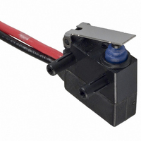
D2HW-BR212MR
Description
SWITCH LEVER SPST-NC 2A SEALED
Manufacturer
Omron
Series
D2HWr
Type
Snap Actionr
Specifications of D2HW-BR212MR
Circuit
SPST-NC
Switch Function
On-Mom
Contact Rating @ Voltage
2A @ 12VDC
Actuator Type
Lever, Straight
Mounting Type
Chassis Mount
Termination Style
Wire Leads
Operating Force
76gf
Contact Form
SPST - NC
Contact Rating
1 Amp at 24 Volts
Actuator
Lever, Hinge
Post Position
Right
Microswitch Type
Ultra Subminiature
Actuator Style
Hinge Lever
Switch Operation
ON-OFF
Operating Force Max
76gf
Contact Voltage Ac Nom
125V
Contact Voltage Dc Nom
42V
Pole Throw Configuration
SPST
Switch Function Configuration
N.C.
Current Rating (max)
2A
Ac Voltage Rating (max)
125VVAC
Dc Voltage Rating (max)
42VVDC
Contact Material
Gold Alloy
Mechanical Life
1000000
Terminal Type
Wire Lead
Product Height (mm)
17.8mm
Product Depth (mm)
10.3mm
Operating Temp Range
-40C to 85C
Lead Free Status / RoHS Status
Lead free / RoHS Compliant
Lead Free Status / RoHS Status
Lead free / RoHS Compliant, Lead free / RoHS Compliant
Other names
D2HWBR212MR
SW725
SW725


D2HW
Precautions
Refer to General Information.
■
Degree of Protection
Do not use this product in water. Although molded lead wire mod-
els satisfy the test conditions for the standard given below, this
test is to check the ingress of water into the switch enclosure after
submerging the Switch in water for a given time. Satisfying this
test condition does not mean that the Switch can be used in
water.
IEC Publication 529, degree of protection IP67.
Do not operate the Switch when it is exposed to water spray, or
when water drops adhere to the Switch surface, or during sudden
temperature changes, otherwise water may intrude into the inte-
rior of the Switch due to a suction effect.
Prevent the Switch from coming into contact with oil and chemi-
cals. Otherwise, damage to or deterioration of Switch materials
may result.
Do not use the Switch in areas where it is exposed to silicon
adhesives, oil, or grease, otherwise faulty contact may result due
to the generation of silicon oxide.
Terminal Connection
When soldering the lead wire to the terminal, first insert the lead
wire conductor through the terminal hole and then conduct sol-
dering.
The rough standard for soldering work is as follows:
Capacity of soldering iron: 50 W Max (300 °C at the iron tip)
Soldering time: 3 seconds max.
Not applying any external force for 1 minute after soldering.
Applying only the minimum required amount of flux. It can cause
a contact failure if flux enters the switch.
Improper soldering involving an excessively high temperature or
excessive soldering time may deteriorate the characteristics of
the Switch.
In case of automatic soldering, please do not apply the heat
beyond 260 °C within 5 seconds.
Pay careful attention so that flux or solder liquid does not exceed
the PCB panel.
Side-actuated (Cam/Dog) Operation
When using a cam or dog to operate the Switch, factors such as
the operating speed, operating frequency, push-button indenta-
tion, and material and shape of the cam or dog will affect the
durability of the Switch. Confirm performance specifications under
actual operation conditions before using the Switch in applica-
tions.
8
Cat. No. B105-E1-05
Cautions
ALL DIMENSIONS SHOWN ARE IN MILLIMETERS.
To convert millimeters into inches, multiply by 0.03937. To convert grams into ounces, multiply by 0.03527.
■
Mounting
Turn OFF the power supply before mounting or removing the
Switch, wiring, or performing maintenance or inspection. Failure
to do so may result in electric shock or burning.
For M3-screw mounting models, use M3 mounting screws with
plane washers or spring washers to securely mount the Switch.
Tighten the screws to a torque of 0.27 to 0.29 N·m. Exceeding the
specified torque may result in deterioration of the sealing or dam-
age.
For models with posts, secure the posts by thermal caulking or by
pressing into an attached device. When pressed into an attached
device, provide guides on the opposite ends of the posts to
ensure that they do not fall out or rattle.
Mount the Switch onto a flat surface. Mounting on an uneven sur-
face may cause deformation of the Switch, resulting in faulty oper-
ation or damage.
Operating Body
Use an operating body with low frictional resistance and of a
shape that will not interfere with the sealing rubber, otherwise the
plunger may be damaged or the sealing may deteriorate.
Handling
Do not handle the Switch in a way that may cause damage to the
sealing rubber.
When handling the Switch, ensure that pressure is not applied to
the posts in the directions shown in the following diagram. Also,
ensure that uneven pressure or pressure in a direction other than
the operating direction is not applied to the Actuator as shown in
the following diagram. Otherwise, the post, Actuator, or Switch
may be damaged, or the service life may be reduced.
Wiring Molded Lead Wire Models
When wiring molded lead wire models, ensure that there is no
weight on the wire or that there are no sharp bends near the parts
where the wire is drawn out. Otherwise, damage to the Switch or
deterioration in the sealing may result.
Using Micro Loads
Even when using micro load models within the operating range,
inrush currents or surges may decrease the life expectancy of the
Switch. Therefore, insert a contact protection circuit where neces-
sary.
Correct Use
D2HW
Related parts for D2HW-BR212MR
Image
Part Number
Description
Manufacturer
Datasheet
Request
R

Part Number:
Description:
SWITCH SUBMINIATURE BASIC SPDT
Manufacturer:
Omron
Datasheet:
Part Number:
Description:
SWITCH SUBMINIATURE BASIC SPDT
Manufacturer:
Omron
Datasheet:
Part Number:
Description:
SWITCH SUBMINI BASIC SPDT-NO
Manufacturer:
Omron
Datasheet:
Part Number:
Description:
SWITCH SUBMINIATURE BASIC SPDT
Manufacturer:
Omron
Datasheet:
Part Number:
Description:
SWITCH SUBMINI BASIC SPST-NO
Manufacturer:
Omron
Datasheet:

Part Number:
Description:
SWITCH SUBMINI BASIC SPDT-NO
Manufacturer:
Omron
Datasheet:

Part Number:
Description:
SWITCH BASIC SPDT 2A SEALED
Manufacturer:
Omron
Datasheet:

Part Number:
Description:
SWITCH LEVER SPDT 2A SEALED
Manufacturer:
Omron
Datasheet:

Part Number:
Description:
SWITCH BASIC SPDT 2A SEALED
Manufacturer:
Omron
Datasheet:

Part Number:
Description:
SWITCH LEVER SPDT 2A SEALED
Manufacturer:
Omron
Datasheet:

Part Number:
Description:
SWITCH LEVER SPDT 2A SEALED
Manufacturer:
Omron
Datasheet:

Part Number:
Description:
SWITCH BASIC SPDT 2A SEALED
Manufacturer:
Omron
Datasheet:

Part Number:
Description:
SWITCH ROLL SPDT 2A SEALED
Manufacturer:
Omron
Datasheet:

Part Number:
Description:
SWITCH LEVER SPDT 2A SEALED
Manufacturer:
Omron
Datasheet:

Part Number:
Description:
SWITCH LEVER SPST-NO 2A SEALED
Manufacturer:
Omron
Datasheet: