D2HW-BR212MR Omron, D2HW-BR212MR Datasheet - Page 5
D2HW-BR212MR
Manufacturer Part Number
D2HW-BR212MR
Description
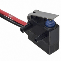
SWITCH LEVER SPST-NC 2A SEALED
Manufacturer
Omron
Series
D2HWr
Type
Snap Actionr
Specifications of D2HW-BR212MR
Circuit
SPST-NC
Switch Function
On-Mom
Contact Rating @ Voltage
2A @ 12VDC
Actuator Type
Lever, Straight
Mounting Type
Chassis Mount
Termination Style
Wire Leads
Operating Force
76gf
Contact Form
SPST - NC
Contact Rating
1 Amp at 24 Volts
Actuator
Lever, Hinge
Post Position
Right
Microswitch Type
Ultra Subminiature
Actuator Style
Hinge Lever
Switch Operation
ON-OFF
Operating Force Max
76gf
Contact Voltage Ac Nom
125V
Contact Voltage Dc Nom
42V
Pole Throw Configuration
SPST
Switch Function Configuration
N.C.
Current Rating (max)
2A
Ac Voltage Rating (max)
125VVAC
Dc Voltage Rating (max)
42VVDC
Contact Material
Gold Alloy
Mechanical Life
1000000
Terminal Type
Wire Lead
Product Height (mm)
17.8mm
Product Depth (mm)
10.3mm
Operating Temp Range
-40C to 85C
Lead Free Status / RoHS Status
Lead free / RoHS Compliant
Lead Free Status / RoHS Status
Lead free / RoHS Compliant, Lead free / RoHS Compliant
Other names
D2HWBR212MR
SW725
SW725


Dimensions
■ Mounting Structure and Reference Positions for Operating Characteristics
Note: 1. All units are in millimeters unless otherwise indicated.
■ Terminals
Lead Wires on Left-side
Reference
position
Models without Posts
D2HW-A@
PCB Cutout Dimensions (Reference)
Straight PCB Terminals
Angled terminal directions are shown below.
Left-angled terminal
2. Dimensions not indicated in the diagrams have a tolerance of ±0.2 mm
3. The reference positions used for FP, OP, and TTP values are as shown below for each type of mounting.
Three, 1
+0.1
0
dia. hole
Three-0.6
1.7 dia.
Right-angled terminal
(13.3)
2.4
(depth: 5 mm min.)
+0.1
0
Reference
position
dia. hole
Note: UL1007 AWG24 wires are used for UL/CSA approved models.
Models with Posts
D2HW-B@
(12)
2.4
(depth: 5 mm min.)
(12)
Mounting Hole Dimensions (Reference) Mounting Hole Dimensions (Reference)
Lead Wires on Right-side
1.7 dia.
+0.1
0
Angled PCB Terminals
PCB Cutout Dimensions (Reference)
dia. hole
(13.3)
2.6
Three-0.6
Sealed Subminiature Snap Action Switch
Three, 1
2.6
(3.1)
+0.1
0
dia. hole
M3-screw Mounting Models
D2HW-C@
Reference
position
(12)
Lead Wires Downwards
3
(depth: 1.5 mm min.)
3
+0.1
−0.1
0
0
Solder Terminals
dia.
dia. hole
M3 tap
Three-2
COM AVSS 0.5
(Black)
NO AVSS 0.5 (Blue)
NC AVSS 0.5 (Red)
See Note
3.3±0.15 dia.
3.5
D2HW
185
Related parts for D2HW-BR212MR
Image
Part Number
Description
Manufacturer
Datasheet
Request
R

Part Number:
Description:
SWITCH SUBMINIATURE BASIC SPDT
Manufacturer:
Omron
Datasheet:
Part Number:
Description:
SWITCH SUBMINIATURE BASIC SPDT
Manufacturer:
Omron
Datasheet:
Part Number:
Description:
SWITCH SUBMINI BASIC SPDT-NO
Manufacturer:
Omron
Datasheet:
Part Number:
Description:
SWITCH SUBMINIATURE BASIC SPDT
Manufacturer:
Omron
Datasheet:
Part Number:
Description:
SWITCH SUBMINI BASIC SPST-NO
Manufacturer:
Omron
Datasheet:

Part Number:
Description:
SWITCH SUBMINI BASIC SPDT-NO
Manufacturer:
Omron
Datasheet:

Part Number:
Description:
SWITCH BASIC SPDT 2A SEALED
Manufacturer:
Omron
Datasheet:

Part Number:
Description:
SWITCH LEVER SPDT 2A SEALED
Manufacturer:
Omron
Datasheet:

Part Number:
Description:
SWITCH BASIC SPDT 2A SEALED
Manufacturer:
Omron
Datasheet:

Part Number:
Description:
SWITCH LEVER SPDT 2A SEALED
Manufacturer:
Omron
Datasheet:

Part Number:
Description:
SWITCH LEVER SPDT 2A SEALED
Manufacturer:
Omron
Datasheet:

Part Number:
Description:
SWITCH BASIC SPDT 2A SEALED
Manufacturer:
Omron
Datasheet:

Part Number:
Description:
SWITCH ROLL SPDT 2A SEALED
Manufacturer:
Omron
Datasheet:

Part Number:
Description:
SWITCH LEVER SPDT 2A SEALED
Manufacturer:
Omron
Datasheet:

Part Number:
Description:
SWITCH LEVER SPST-NO 2A SEALED
Manufacturer:
Omron
Datasheet: