HBS2KCB4SD055C C&K Components, HBS2KCB4SD055C Datasheet - Page 4
HBS2KCB4SD055C
Manufacturer Part Number
HBS2KCB4SD055C
Description
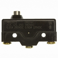
SWITCH SNAP SPDT 20A STUB PLUNGR
Manufacturer
C&K Components
Series
HBr
Datasheet
1.HBS2KGB4ST011C.pdf
(6 pages)
Specifications of HBS2KCB4SD055C
Circuit
SPDT
Switch Function
On-Mom
Contact Rating @ Voltage
20A @ 125VAC
Actuator Type
Round (Pin Plunger)
Mounting Type
Chassis Mount
Termination Style
Screw Terminal
Operating Force
370gf
Pole Throw Configuration
SPDT
Switch Function Configuration
N.O./N.C.
Actuator Style
Stub Plunger
Actuator Material
Phenolic
Current Rating (max)
20A
Ac Voltage Rating (max)
480VVAC
Dc Voltage Rating (max)
250VVDC
Contact Material
Fine Silver
Mechanical Life
150000
Terminal Type
Screw
Product Depth (mm)
17.5mm
Operating Temp Range
-55C to 150C
Mounting Style
Through Hole
Contact Form
SPDT
Contact Rating
20 Amps
Actuator
Plunger
Lead Free Status / RoHS Status
Lead free / RoHS Compliant
Other names
*HBS2KCB4SD055C
CKN9872
CKN9872


J
HB Series
Single Pole Standard Precision Snap-acting Switches
NOTE: Mounting holes will accept pins or screws of .139 dia. (3,53) max. on
1.000 ± .002 (25,4 ± 0,05) centers.
* Actuators sealed against the entrance of airborne
B? .040
S
contaminants and/or splashing liquids.
OPTION CODE
C
Standard
TS*
A0
D0
P0
R5
F0
J0
T0
Y0
D
POLES
Plunger
FIG. 4
NO.
SP
SP
SP
SP
SP
SP
SP
SP
SP
A
FIG.
1
2
4
5
6
7
7
3
8
DIM. A
(33,27)
(21,8)
(21,8)
(23,4)
(23,4)
1.310
(37,3)
(23,4)
(2,3)
1.47
(1,3)
.86
.09
.86
.92
.92
Reverse Acting Lever
.92
.05
D
PANEL MOUNTING
FIG. 8
MOUNTING STYLE
(28,45 ± 1,52)
(28,45 ± 1,27)
(15,88 ± 0,25)
(18,28 ± 1,52)
(18,28 ± 1,52)
(21,44 ± 0,51)
(18,29 ± 0,76)
1.120 ± .060
1.120 ± .050
(21,84±0,76)
.625 ± .010
.720 ± .060
.720 ± .060
.844 ± .020
.720 ± .030
.860±.030
.50 DIA.
(12,70?)
DIM. B
C
(15,7)
.62
ACTUATOR
A
1.03 dia.
1.03 dia.
DIM. C
.38 dia.
.38 dia.
.64 dia.
.50 dia.
(26,2Ø))
(16,3Ø)
(12,7Ø)
(26,2Ø)
.74 dia.
(18,8Ø)
(9,7Ø)
(9,7Ø)
—
—
B
B
DIM. D
(26,2)
(18,8)
(8,40)
(15,5)
1.03
(6,73)
0.33
0.61
2.65
.74
—
—
—
—
Pin Plunger
J–52
FIG. 5
A
Lever Roller
FIG.
D
1
B
FIG. 7
Lever
C
A
Stub Plunger
NOTE: Torque mounting screws 3 inlbs max.
A
B
C
Specifications and dimensions subject to change
A
B
FIG. 3
A
D
B
www.ck-components.com
Perpendicular Roller Plunger
Dimensions are shown: Inch (mm)
Lever Roller
FIG. 6
FIG. 2
D
C
C
A
B
Related parts for HBS2KCB4SD055C
Image
Part Number
Description
Manufacturer
Datasheet
Request
R

Part Number:
Description:
Rotary Switches 4P 3 POS ROTARY SW
Manufacturer:
C&K Components
Part Number:
Description:
ANALOG ROCKER C&K DELTATECH
Manufacturer:
C&K Components
Part Number:
Description:
QUARDANT MODUL C&K DELTATECH
Manufacturer:
C&K Components
Datasheet:
Part Number:
Description:
TOGGLE,THT-PC,SPDT,ON-OFF-ON,ACT-DXL:6.09X17.15MM,BUSH-THREADED,AU
Manufacturer:
C&K Components
Part Number:
Description:
SMARTCARD CONNECTOR *Y1112-2013AP LFT
Manufacturer:
C&K Components
Part Number:
Description:
Connector reel; SIM card; 6 contacts; hinged; no switch lock
Manufacturer:
C&K Components
Part Number:
Description:
CCM03-MKII SmartCard Conn for SIM/SAM cards, 6-contacts hinged 1k reel
Manufacturer:
C&K Components