D2SW-3L1H Omron, D2SW-3L1H Datasheet - Page 2
D2SW-3L1H
Manufacturer Part Number
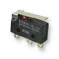
D2SW-3L1H
Description
MINIATURE BASIC SWITCH
Manufacturer
Omron
Series
D2SWr
Specifications of D2SW-3L1H
Operating Force
60gf
Circuit
SPDT
Switch Function
On-Mom
Contact Rating @ Voltage
3A @ 125VAC
Actuator Type
Lever, Straight
Mounting Type
Chassis Mount
Termination Style
Solder Lug
Contact Configuration
SPDT
Microswitch Type
Snap Action
Actuation Type
Lever
Contact Voltage Ac Nom
250V
Contact Voltage Dc Nom
30V
Contact Current Max
3A
Switch Terminals
Solder
Actuator Style
Lever
Operating Force Max
0.59N
Rohs Compliant
Yes
Lead Free Status / RoHS Status
Lead free / RoHS Compliant
Other names
D2SW3L1H
Available stocks
Company
Part Number
Manufacturer
Quantity
Price


Specifications
■ Characteristics
Note: 1. Data shown are of initial value.
■ Ratings
D2SW-3
D2SW-01
Note: 1. The resistive load ratings apply under the following test conditions:
196
Operating speed
Operating frequency
Insulation resistance
Contact resistance
Dielectric strength (See note 2)
Vibration resistance (See note 3)
Shock resistance (See note 3)
Ambient operating temperature
Ambient operating humidity
Degree of protection
Degree of protection against electric shock
Proof tracking index (PTI)
Life expectancy
Weight
125 VAC
250 VAC
30 VDC
125 VAC
30 VDC
2. The dielectric strength shown is measured using a separator between the switch and metal mounting plate
3. For pin plunger models, the above values apply for use at the free position, operating position, and total travel position. For models with
2. The above current ratings are the values of the steady-state current.
3. Inductive load has a power factor of 0.7 min. (AC) and a time constant of 7 ms max. (DC).
4. Lamp load has an inrush current of 10 times the steady-state current.
5. Motor load has an inrush current of 6 times the steady-state current.
Rated Voltage
Rated Voltage
levers, the values apply at the total travel position.
Ambient Temperature = 20±2°C, Ambient Humidity = 65±5%, Operating frequency = 30 operations/min.
Sealed Snap Action Switch
(reference values)
Item
Mechanical
Electrical
(30 operations per minute)
Terminal model
Lead wire model
3 A
2 A
3 A
0.1 A
0.1 A
NC
NC
Resistive load
Resistive load
Non-inductive load (A)
Non-inductive load
D2SW
NO
NO
0.1 mm to 1 m/second (at pin plunger)
Mechanical: 300 operations/minute max.
Electrical: 30 operations/minute max.
100 MΩ min. (at 500 VDC)
30 mΩ max. for terminal models
50 mΩ max. for lead wire models
1,000 VAC, 50/60 Hz for 1 min. between
terminals of the same polarity
1,500 VAC, 50/60 Hz for 1 min. between current-carrying metal parts and ground, and
between each terminal and noncurrent-carrying metal parts
Malfunction: 10 to 55 Hz, 1.5 mm double amplitude
Destruction: 1,000 m/s
Malfunction: 300 m/s
-40° to 85°C (at 60% RH) with no icing
95% max. (for 5°C to 35°C)
IEC IP67 (excluding the terminals on terminal models)
Class I
175
5,000,000 operations min. at 60 operations per minute
200,000 operations min. (3 A at 125 VAC)
100,000 operations min. (2 A at 250 VAC)
Approx. 2 g
Approx. 10 g
1 A
0.5 A
1 A
—
—
NC
NC
Lamp load
Lamp load
D2SW-3
0.5 A
0.3 A
2
(approx. 30G) max.
NO
NO
2
(approx. 100G) max.
1 A
0.5 A
1 A
—
—
NC
NC
Inductive load
Inductive load
50 mΩ max. for terminal models
70 mΩ max. for lead wire models
600 VAC, 50/60 Hz for 1 min. between ter-
minals of the same polarity
200,000 operations min.
(at rated resistive load)
0.5 A
0.3 A
NO
NO
Inductive load
Inductive load
1 A
0.5 A
1 A
—
—
D2SW-01
NC
NC
Motor load
Motor load
0.5 A
0.3 A
NO
NO
Related parts for D2SW-3L1H
Image
Part Number
Description
Manufacturer
Datasheet
Request
R

Part Number:
Description:
MINIATURE BASIC SWITCH
Manufacturer:
Omron
Datasheet:
Part Number:
Description:
MINIATURE BASIC SWITCH
Manufacturer:
Omron
Datasheet:

Part Number:
Description:
SWITCH 3A BASIC SEALED SLDR TERM
Manufacturer:
Omron
Datasheet:

Part Number:
Description:
SWITCH 3A LEVER SEALED SLD TERM
Manufacturer:
Omron
Datasheet:

Part Number:
Description:
SWITCH 3A LEVER SEALED SLD TERM
Manufacturer:
Omron
Datasheet:

Part Number:
Description:
SWITCH 3A ROLLER SEALED SLDR
Manufacturer:
Omron
Datasheet:

Part Number:
Description:
SWITCH 3A LEVER SEALED 12"WIRES
Manufacturer:
Omron
Datasheet:

Part Number:
Description:
SWITCH 3A LEVER SEALED 12"WIRES
Manufacturer:
Omron
Datasheet:

Part Number:
Description:
SWITCH 3A ROLLER SEALED 12"WIRES
Manufacturer:
Omron
Datasheet:

Part Number:
Description:
SWITCH 3A BASIC SEALED .110QC
Manufacturer:
Omron
Datasheet:

Part Number:
Description:
SWITCH 3A BASIC SEALED PC MNT
Manufacturer:
Omron
Datasheet:

Part Number:
Description:
SWITCH 3A LEVER SEALED .110QC
Manufacturer:
Omron
Datasheet:

Part Number:
Description:
SWITCH 3A BASIC SEALED 12"WIRES
Manufacturer:
Omron
Datasheet:

Part Number:
Description:
MINIATURE BASIC SWITCH
Manufacturer:
Omron
Datasheet:

Part Number:
Description:
SUBMINIATURE BASIC SWITCH
Manufacturer:
Omron
Datasheet: