307001120 Molex Inc, 307001120 Datasheet
307001120
Specifications of 307001120
307001120
WM4325
Available stocks


Related parts for 307001120


307001120 Summary of contents
Page 1
HDAC .64 User Manual Connector Assembly Reference Manual REV 1 – May 9, 2006 ...
Page 2
Table of Contents Section 1: Product Introduction Section 2: Product Summary Section 3: Connector Assembly Section 4: Connector Mating Section 5: Service Instructions HDAC 0.64 User Manual 2 ...
Page 3
Product Introduction HDAC 0.64 Product Line HDAC 0.64 User Manual 3 ...
Page 4
Section 1: Product Introduction This instructions manual contains supplemental information pertaining to the Molex HDAC 0.64 Product Line. For product ordering information, please contact your Molex Inside Sales Representative at (800)786-6539. For electronic copies and future updates of this document, ...
Page 5
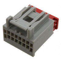
Section 2: Product Summary A. Connector Assemblies HDAC 0.64 Receptacle Connector Assembly HDAC 0.64 User Manual HDAC 0.64 Blade Connector Assembly Housing TPA 5 ...
Page 6
Section 2: Product Summary TYCO Blade Terminal • Base Material Copper Alloy • Plating Options Tin, Gold • Wire Sizes: 16,18,20,22 AWG Molex Receptacle Terminal PN 34083-3001 • Base Material Copper Alloy • Plating Options Tin, Gold • Wire Sizes: ...
Page 7
Section 3: Connector Assembly A. Connectors shown in “As Shipped” Connector Position TPA’s shown in “as shipped” condition (pre-lock). The TPA must remain in the pre-lock position until all circuits are loaded. HDAC 0.64 User Manual 7 ...
Page 8
Section 3: Connector Assembly B. Terminal Installation: With TPA still in pre-lock position, orient terminal to rear of connector as shown below. Grip the wire no less than 1.25 inches from the terminal insulation crimp and insert through appropriate circuit ...
Page 9
Section 3: Connector Assembly C. Seating the TPA With the receptacle terminals fully installed, the TPA can be seated into its final lock position by applying an even force to the TPA surface until it comes to a stop, with ...
Page 10
Section 4: Connector Mating Keying Features HDAC 0.64 User Manual Note and align connector keying features, from receptacle connector to blade connector. Begin mating procedure by sliding the receptacle connector assembly and blade connector assembly together, press firmly until you ...
Page 11
Section 5: Service Instructions A. Un-mate procedure To un-mate the connectors, push connector together to unload the latch system. Than depress the latch with your thumb (step 1). Continue to depress the latch, and gently pull apart connector assemblies (step2). ...
Page 12
Section 5: Service Instructions B. TPA Servicing Receptacle Step 1: Insert a small screwdriver, or service tool (max width = 2.0 mm) into the designated pry point. Step 2: Using the housing as a pivot point gently push out on ...
Page 13
Section 5: Service Instructions C. TPA servicing the Blade connector Step 1: Insert a small screwdriver into the two small extraction holes Step 2: Push on opposite sides of the TPA latch until it is removed from the connector housing. ...
Page 14
Section 5: Service Instructions D. Terminal removal (continued) Step 3: Service tool should not be more than 2.0 mm wide. Using the designated service tool, disengage the terminal lock finger. Once the Lock finger is disengaged, gently pull on the ...