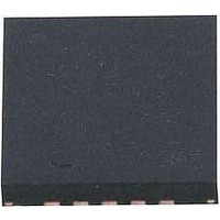
AT42QT1070-MMH Atmel, AT42QT1070-MMH Datasheet - Page 56

AT42QT1070-MMH
Manufacturer Part Number
AT42QT1070-MMH
Description
IC TOUCH SENSOR 7KEY 20-VQFN
Manufacturer
Atmel
Type
Capacitiver
Specifications of AT42QT1070-MMH
Number Of Inputs/keys
7 Key (Comms), 5 Key (Standalone)
Data Interface
I²C
Voltage Reference
Internal
Voltage - Supply
1.8 V ~ 5.5 V
Operating Temperature
-40°C ~ 85°C
Mounting Type
Surface Mount
Package / Case
20-VFQFN Exposed Pad
Supply Voltage
1.8 V to 5.5 V
Dimensions
3 mm L x 3 mm W x 0.8 mm H
Temperature Range
- 40 C to + 85 C
Termination Style
SMD/SMT
Lead Free Status / RoHS Status
Lead free / RoHS Compliant
Current - Supply
-
Resolution (bits)
-
Touch Panel Interface
-
Data Rate/sampling Rate (sps, Bps)
-
Lead Free Status / Rohs Status
Lead free / RoHS Compliant
Available stocks
Company
Part Number
Manufacturer
Quantity
Price
Company:
Part Number:
AT42QT1070-MMH QS529
Manufacturer:
Atmel
Quantity:
9 390
10620D–AT42–04/09
Mutual-capacitance One-dimensional Sensors
6.3
6.3.1
6.3.2
6.3.2.1
6-2
Typical Spatially Interpolated Method
Introduction
One-Layer Small Slider Or Wheel
Slider
This method uses an array of keys directly adjacent to each other.
There are numerous ways to construct a spatially interpolated slider, but the most basic form is to use an
array of keys as shown in
n x 6 mm to n x 8 mm in length, where n is the number of keys used. For larger sliders use a resistively
interpolated design (see
From
and Y fingers for design purposes. There is no border between the keys, only at either end of the slider.
Instead, an "extra" Y finger is inserted between each key.
Note:
Figure 6-1.
Given the widths of the Y and X traces, you will need to calculate the number of X fingers (X
will fit in the slider, allowing for end borders of at least T wide. Any unallocated width remaining after the
number of fingers has been calculated is added to the end of the slider, so the width of the end borders
(X
X
border
border
Y
(Typically
0.1–0.5 mm)*
width
Figure 6-1
T/2
T/2
³
) must also be calculated.
T
This method by its nature has the electrodes arranged on a single layer, which means that Y
electrode cuts through the X electrodes. Jumpers or vias are therefore required to connect the
isolated X regions to the interdigitated X regions.
One-layer Small Slider (Spatially Interpolated)
it can be seen that the slider can be treated as one large “super key” of interdigitated X
X3
Section 6.4 “Typical Resistively Interpolated Method” on page 6-10
Between Xs
Y
Figure 6-1 on page
T/2
width
Gap
W (6–8 mm)
X2
X electrodes require a
jumper or via to connect
the
6-2. It is suitable for sliders that are approximately
two isolated X regions
L
.
X1
Touch Sensors Design Guide
T
X0
T/2
).
fingers
5 50 mm
–
) that


