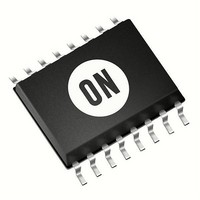
CAT4106YP-T2 ON Semiconductor, CAT4106YP-T2 Datasheet - Page 10

CAT4106YP-T2
Manufacturer Part Number
CAT4106YP-T2
Description
LED Drivers LED DRVR BOOST 4CH/10LED
Manufacturer
ON Semiconductor
Datasheet
1.CAT4106HV4-GT2.pdf
(15 pages)
Specifications of CAT4106YP-T2
Number Of Digits
4
Low Level Output Current
10 mA
High Level Output Current
175 mA
Operating Supply Voltage
- 0.3 V to 6 V
Maximum Supply Current
4.4 mA
Maximum Operating Temperature
+ 85 C
Mounting Style
SMD/SMT
Package / Case
TSSOP-16
Minimum Operating Temperature
- 40 C
Lead Free Status / RoHS Status
Lead free / RoHS Compliant
Available stocks
Company
Part Number
Manufacturer
Quantity
Price
Company:
Part Number:
CAT4106YP-T2
Manufacturer:
ON Semiconductor
Quantity:
1 978
Company:
Part Number:
CAT4106YP-T2
Manufacturer:
ON Semiconductor
Quantity:
950
Device Operation
consisting of up to four separate strings. A single external
resistor value is used to select the drive level in all output
channels. Each channel provides a very well regulated and
tightly matched bias current on all LED strings.
the high voltage output required to power the LED strings.
Up to a maximum of 6 W of LED power can be delivered
when powered from a 12 V supply.
user to set the operating voltage level on the output drive
channels. A pair of external resistors is used to control the
nominal channel voltage, during normal operation. The
resulting output voltage (LED anodes) will be equal to the
sum of the adjusted channel voltage plus the maximum
forward voltage present on any string.
to accurately regulate LED current in each channel. Up to
175 mA per channel can be programmed by selecting a
suitable value for the external R1 resistor (connected
between RSET and GND pins).
LED Current Setting
to accurately regulate LED current in each channel. The
LED current is set by the external resistor R1 connected
between the RSET pin and ground. The following formula
gives the relationship between the resistor value and the
LED current per channel.
Setting the Channel Voltage
headroom for full load operation. The lowest channel
operating voltage can be controlled and programmed via the
external resistor network connected between, CTRL, FB
and GND as shown in Figure 24.
recommended. The CTRL output pin has optimal
performance when loaded with around 15 mA, which
equates to an R3 resistor value of 20 kW.
Table 6. RESISTOR R1 AND LED CURRENT
In a typical application, the CAT4106 drives an LED array
An integrated DC/DC boost converter is used to generate
To offer improved performance, the device also allows the
The CAT4106 provides four tightly matched current sinks
The CAT4106 provides four tightly matched current sinks
Each LED channel typically requires less than 0.5 V of
For most applications, a gain of 2x (R2 equals R3) is
LED Current per Channel (mA)
Lowest LED pin voltage + V
R1 [ 103
100
150
10
20
30
50
LED current per channel
1.2 V
FB
R2 ) R3
R3
R1 (W)
12.4 k
6.19 k
4.12 k
2.49 k
1.24 k
820
http://onsemi.com
10
LED Detection
LED load, such as if one of the LED strings has been
disconnected (Open−LED) or if one LED string has a lower
LED pin voltage than expected (Short−LED). Either
condition is flagged by turning on the open−drain output on
the FAULT pin. The Open−LED detection is active in
normal operation. The Short−LED detection is only active
during power−up, just after the EN/PWM input goes from
low to high. If in normal operation (LEDs are in regulation)
a short−LED condition occurs, it will not be detected.
shorted to the output (top LED anode). The test condition in
Figure 26 is with one LED pin floating or disconnected. In
both cases, the CAT4106 is set to drive 50 mA per channel.
Setting VFMIN Level (Short−LED)
for the LED string voltage “window of operation”. This
voltage setting is based on the number of series LEDs being
used and the expected minimum forward voltage V
normal operation.
Example: Consider a string of 6 LEDs in series, with each
LED having a V
minimum V
expected string voltage would be 18 V. Any string voltage
of less than 18 V is considered as a short−circuit fault in one
or more of the series LEDs.
The CAT4106 detects failure conditions related to the
The test condition in Figure 25 is with one LED pin
The VFMIN level represents the minimum level expected
Figure 26. Normal Operation Open−LED Detection
Figure 25. Cold Power−Up Short−LED Detection
F
of each LED is 3.0 V the overall lowest
F
range of 3.5 V ± 0.5 V. Since the
F
during


