MTF-TQ35SN741-AV Microtips Technology, MTF-TQ35SN741-AV Datasheet - Page 9
MTF-TQ35SN741-AV
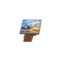
Manufacturer Part Number
MTF-TQ35SN741-AV
Description
TFT Displays & Accessories 320 x 240 TFT 3.5 diag
Manufacturer
Microtips Technology
Datasheet
1.MTF-TQ35SN741-AV.pdf
(29 pages)
Specifications of MTF-TQ35SN741-AV
Lead Free Status / RoHS Status
Lead free / RoHS Compliant


Messrs.
Product Specification
Note 1: SPI Interface is only to set up the initial code in LCM driver IC register.
Note 2: There had been default initial code stored in LCD driver IC at Sync Mode operation, and if customer
Note 3: Different from Sync mode, there is no default initial code in driver IC in DE mode, so initial code has
28
29
30
31
32
33
34
35
36
37
38
39
40
41
42
43
44
45
46
47
48
49
50
51
52
53
54
needs to revise the default initial code to change gamma or Vcom voltage, then SPI interface is
needed.
to be setup via SPI interface at DE mode.
H
GND
GND
V
SDO
SP
DEN
D
N/C
N/C
N/C
N/C
N/C
N/C
N/C
CSB
V
V
SDI
R0
R1
R2
R3
R4
R5
R6
R7
SYNC
SYNC
CLK
CC
CC
CLK
Model:
--
--
--
--
--
--
--
I
I
I
I
I
I
I
I
I
I
I
I
I
I
I
I
I
I
I
I
MTF-TQ35SN741-AV
Red Data Bit0
Red Data Bit1
Red Data Bit2
Red Data Bit3
Red Data Bit4
Red Data Bit5
Red Data Bit6
Red Data Bit7
Horizontal Sync Input
Vertical Sync Input
Dot Data Clock
Not Connection
Not Connection
Digital Power
Digital Power
SPI Interface Data En
Leave it open when not used!
Not Connection
Not Connection
Not Connection
Not Connection
SPI Interface Data output
Leave it open when not used!
SPI Interface Data Clock
Leave it open when not used!
SPI Interface Data input
Leave it open when not used!
Not Connection
Data Enable Input, Internal Pull High (3.1V~3.3V) ,
Connect to 2.5V~3.6V or floating if not used.,
Ground
Ground
Rev. No.
G
Issued Date.
Jun.23, 08
Note 2
Note 2
Note 1
Note 1
Note 1
Note 1
Note 3
3.3V
3.3V
9 / 29
Page.
Related parts for MTF-TQ35SN741-AV
Image
Part Number
Description
Manufacturer
Datasheet
Request
R

Part Number:
Description:
TFT Displays & Accessories 7.0 TFT WVGA Tch Screen 180 Nits
Manufacturer:
Microtips Technology
Datasheet:

Part Number:
Description:
LCD Character Display Modules 20x2 VLCD Character White LED Backlight
Manufacturer:
Microtips Technology
Datasheet:

Part Number:
Description:
LCD Character Display Modules 20x2 VLCD Character Green LED Backlight
Manufacturer:
Microtips Technology
Datasheet:

Part Number:
Description:
LCD Character Display Modules 20x2 VLCD Character Red LED Backlight
Manufacturer:
Microtips Technology
Datasheet:

Part Number:
Description:
LCD Character Display Modules Gray Transflective White LED Backlight
Manufacturer:
Microtips Technology
Datasheet:

Part Number:
Description:
LCD Character Display Modules Gray Reflective
Manufacturer:
Microtips Technology

Part Number:
Description:
LCD Character Display Modules Yl/Grn Transflective Yl/Grn LED Backlight
Manufacturer:
Microtips Technology
Datasheet:
Part Number:
Description:
LCD Character Display Modules Yl/Grn Reflective
Manufacturer:
Microtips Technology
Part Number:
Description:
LCD Character Display Modules Gray Transflective Yl/Grn LED Backlight
Manufacturer:
Microtips Technology

Part Number:
Description:
LCD Character Display Modules Gray Reflective
Manufacturer:
Microtips Technology
Datasheet:
Part Number:
Description:
TFT Displays & Accessories 7.0 TFT WVGA Tch Screen 180 Nits
Manufacturer:
Microtips Technology
Datasheet:

Part Number:
Description:
TFT Displays & Accessories 5.7 TFT VGA WHITE LED 350 Nits
Manufacturer:
Microtips Technology
Datasheet:

Part Number:
Description:
TFT Displays & Accessories 3.5 TFT W/ Touch screen
Manufacturer:
Microtips Technology
Datasheet:

Part Number:
Description:
TFT Displays & Accessories 2.4 TFT ILI9325 TFT driver
Manufacturer:
Microtips Technology
Datasheet:

Part Number:
Description:
TFT Displays & Accessories 3.5 TFT 320x240 Parallel
Manufacturer:
Microtips Technology
Datasheet: