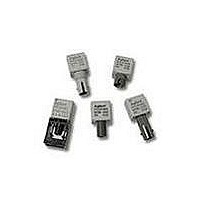
HFBR-2416MZ Avago Technologies US Inc., HFBR-2416MZ Datasheet - Page 16

HFBR-2416MZ
Manufacturer Part Number
HFBR-2416MZ
Description
Fiber Optic Transmitters, Receivers, Transceivers 125MHz Anlg FO ST M Pt Rx Pb-Free
Manufacturer
Avago Technologies US Inc.
Series
HFBR-24xxZr
Datasheet
1.HFBR-4401Z.pdf
(25 pages)
Specifications of HFBR-2416MZ
Function
Optical Receivers for Industrial Application, Analog Output, Metal ST
Product
Receiver
Data Rate
20 to 160 MBd
Wavelength
820 nm
Diode Capacitance
55 pF
Maximum Rise Time
6.3 ns
Maximum Fall Time
6.3 ns
Operating Supply Voltage
4.75 V to 5.25 V
Maximum Operating Temperature
+ 85 C
Minimum Operating Temperature
- 40 C
Current - Supply
6.2mA
Voltage - Supply
4.75 V ~ 5.25 V
Applications
General Purpose
Power - Minimum Receivable
-
Lead Free Status / RoHS Status
Lead free / RoHS Compliant
Power - Minimum Receivable
-
Lead Free Status / Rohs Status
Lead free / RoHS Compliant
For Use With
Multimode Fiber
Lead Free Status / RoHS Status
Lead free / RoHS Compliant, Lead free / RoHS Compliant
Available stocks
Company
Part Number
Manufacturer
Quantity
Price
Company:
Part Number:
HFBR-2416MZ
Manufacturer:
Avago Technologies
Quantity:
135
Company:
Part Number:
HFBR-2416MZ
Manufacturer:
AVAGO
Quantity:
5 000
Electrical/Optical Specifications -40 °C to +85 °C unless otherwise specified.
HFBR-14x2Z Output Power Measured Out of 1 Meter of Cable
16
Parameter
Forward Voltage
Forward Voltage Temperature
Coefficient
Reverse Input Voltage
Peak Emission Wavelength
Diode Capacitance
Optical Power Temperature
Coefficient
Thermal Resistance
14x2Z Numerical Aperture
14x4Z Numerical Aperture
14x2Z Optical Port Diameter
14x4Z Optical Port Diameter
Parameter
50/125 Pm Fiber Cable
62.5/125 Pm Fiber Cable
100/140 Pm Fiber Cable
200 Pm HCS Fiber Cable
CAUTION: The small junction sizes inherent to the design of these components increase the components’ susceptibility
to damage from electrostatic discharge (ESD). It is advised that normal static precautions be taken in handling and
assembly of these components to prevent damage and/or degradation which may be induced by ESD.
Symbol
P T50
P T62
P T100
P T200
Symbol
V
'V
V
l
C
'P
T
NA
NA
D
D
P
JA
F
BR
T
F
T
/'T
/'T
Min
-21.8
-22.8
-20.3
-21.9
-19.0
-20.0
-17.5
-19.1
-15.0
-16.0
-13.5
-15.1
-10.0
-11.0
-8.5
-10.1
Min
1.48
1.8
792
Typ
-18.8
-16.8
-16.0
-14.0
-12.0
-10.0
-7.0
-5.0
Typ
1.70
1.84
-0.22
-0.18
3.8
820
55
-0.006
-0.010
260
0.49
0.31
290
150
2
Max
-16.8
-15.8
-14.4
-13.8
-14.0
-13.0
-11.6
-11.0
-10
-9.0
-7.6
-7.0
-5.0
-4.0
-2.6
-2.0
Max
2.09
865
Units
dBm peak
dBm peak
dBm peak
dBm peak
Units
V
mV/qC
V
nm
pF
dB/qC
qC/W
μm
μm
Conditions
T
I
T
I
T
I
T
I
T
I
T
I
T
I
T
I
F
F
F
F
F
F
F
F
A
A
A
A
A
A
A
A
Conditions
IF = 60 mA dc
IF = 100 mA dc
IF = 60 mA dc
IF = 100 mA dc
IF = 100 μA dc
V = 0, f = 1 MHz
I = 60 mA dc
I = 100 mA dc
= 60mA dc
= 100mA dc
= 60mA dc
= 100mA dc
= 60mA dc
= 100mA dc
= 60mA dc
= 100mA dc
= +25 °C,
= +25 °C,
= +25 °C,
= +25 °C,
= +25 °C,
= +25 °C,
= +25 °C,
= +25 °C,
Reference
Notes 5, 6, 9
Reference
Figure 9
Figure 9
Notes 3, 8
Note 4
Note 4


