ASMT-AN31-NUV01 Avago Technologies US Inc., ASMT-AN31-NUV01 Datasheet
ASMT-AN31-NUV01
Specifications of ASMT-AN31-NUV01


Related parts for ASMT-AN31-NUV01


ASMT-AN31-NUV01 Summary of contents
Page 1
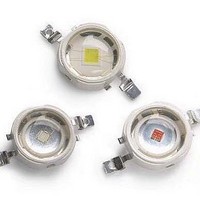
... ASMT-Ax3x 3W Power LED Light Source Data Sheet Description This 3W Power LED Light Source is a high performance energy efficient device which can handle high thermal and high driving current. The exposed pad design enables excellent heat transfer from the package to the mother- board ...
Page 2
... Package Dimensions 7.4 TOP VIEW 2.0 3.0 0.5 6.0 13.6 Figure 1. ASMT-Ax3x package outline drawing Notes: 1. All dimensions in millimeters. 2. Metal slug is connected to anode for electrically non-isolated option. 3. Tolerance is ±0.1 mm unless otherwise specified Terminal Finish: Ag plating 2 1.5 2.3 Ø 8.0 Metal Slug Ø ...
Page 3
... Part Numbering System ASMT – – Note: 1. Please refer to Page 11 for selection details. q Device Selection Guide ( Part Number Color ASMT-AR30-ARS00 Red ASMT-AH30-ARS00 Red Orange ASMT-AA30-ARS00 Amber ASMT-AG31-NTU00 Green ASMT-AB31-NMP00 Blue ASMT-AL31-NPQ00 Royal Blue ASMT-AW31-NUV00 Cool White ASMT-AN31-NUV00 Neutral White ASMT-AY31-NTU00 Warm White Notes: 1. Φ ...
Page 4
... ASMT-AA30-ARS00 Amber ASMT-AG31-NTU00 Green ASMT-AB31-NMP00 Blue ASMT-AL31-NPQ00 Royal Blue Part Number Color ASMT-AW31-NUV00 Cool White ASMT-AN31-NUV00 Neutral White ASMT-AY31-NTU00 Warm White Notes: 1. The dominant wavelength derived from the CIE Chromaticity Diagram and represents the color of the device T½ is the off-axis angle where the luminous intensity is ½ the peak intensity. ...
Page 5
... Optical and Electrical Characteristic at 700 mA (T Part Number Color ASMT-AR30-ARS00 Red ASMT-AH30-ARS00 Red Orange ASMT-AA30-ARS00 Amber ASMT-AG31-NTU00 Green ASMT-AB31-NMP00 Blue ASMT-AL31-NPQ00 Royal Blue ASMT-AW31-NUV00 Cool White ASMT-AN31-NUV00 Neutral White ASMT-AY31-NTU00 Warm White 5 Typ Max. 2.1 2.3 3.2 3.5 = 25°C) J Luminous Flux (lm) ...
Page 6
AlInGaP 1 0.9 AMBER 0.8 RED ORANGE RED 0.7 0.6 0.5 0.4 0.3 0.2 0.1 0 530 545 560 575 590 605 620 635 650 665 680 WAVELENGTH - nm Figure 2. Relative Intensity vs. Wavelength for Red, Red Orange ...
Page 7
AlInGaP 220.0 200.0 180.0 160.0 140.0 120.0 100.0 80.0 60.0 RED ORANGE 40.0 RED AMBER 20.0 0.0 -50 - JUNCTION TEMPERATURE, T Figure 8. Relative Light Output vs. Junction Temperature. 800 700 600 500 400 Rθ = 20°C/W ...
Page 8
InGaN 1.0 0.9 0.8 0.7 0.6 0.5 0.4 0.3 0.2 0.1 0.0 380 430 480 530 580 WAVELENGTH - nm Figure 12. Relative Intensity vs. Wavelength for Warm White and Cool White. 2 1.8 1.6 1.4 1.2 1 0.8 0.6 ...
Page 9
InGaN 1.4 1.2 1.0 0.8 0.6 0.4 0.2 0.0 0.00001 0.0001 0.001 0.01 0.1 PULSE DURATION, t Figure 18. Maximum pulse current vs. ambient temperature. Derated based 25° 30°C/W. A J-A 120.0 110.0 100.0 90.0 ...
Page 10
Figure 24. Recommended soldering land pattern. 255 - 260°C 3°C/SEC. MAX. 217°C 200°C 150°C 3°C/SEC. MAX 120 SEC. TIME Figure 26. Recommended Reflow Soldering. Note: For detail information on reflow soldering of Avago surface ...
Page 11
... Option Selection Details ASMT – – Minimum Flux Bin Selection 4 x – Maximum Flux Bin Selection 5 x – Color Bin Selection 6 x – Packaging Option 7 Color Bin Selection [ Individual reel or tube will contain parts from one color bin selection only. Cool White ...
Page 12
VM 6300K 0. 7000K 0. 0.32 WP 10000K 0.30 YA 0.28 0.26 0.26 0.28 0.30 0.32 0.34 X-COORDINATE Figure 27. Color bin structure ...
Page 13
Color Bin Limit Cool Color Limits White (Chromaticity Coordinates) Bin UM x 0.365 0.367 y 0.386 0.400 Bin UN x 0.365 0.362 y 0.386 0.372 Bin U0 x 0.362 0.360 y 0.372 0.357 Bin UP x 0.360 0.357 y 0.357 ...
Page 14
... Tolerance: ±1 nm 0.362 0.365 0.372 0.386 0.360 0.362 0.357 0.372 Color 0.357 0.360 Royal Blue 0.342 0.357 Tolerance: ±2 nm Example ASMT-AW31-NUV00 ASMT-AW31-Nxxxx – Dominant Wavelength (nm) at 350 mA Bin ID Min. Max. - 620.0 635.0 - 610.0 620.0 B 587 ...
Page 15
Packing Tube – Option 0 17.2 ±0.1 0.4 ±0.1 7.3 ±0.1 Figure 30. Package tube dimensions. 15 ...
Page 16
Tape and Reel – Option 1 4.00 ±0.10 2.00 ±0. 12.00 ±0.10 Figure 31. Carrier tape dimensions. Figure 32. Reel dimensions. 16 +0.10 Ø 1.50 0. ‘AO’ 8.10 ±0.10 Section 'A-A' Ø 330.0 ± 2.0 Detail ...
Page 17
Handling Precaution The encapsulation material of the product is made of silicone for better reliability of the product. As silicone is a soft material, please do not press on the silicone or poke a sharp object onto the silicone. These ...