LZ1-10R105 LedEngin, LZ1-10R105 Datasheet
LZ1-10R105
Specifications of LZ1-10R105


Related parts for LZ1-10R105


LZ1-10R105 Summary of contents
Page 1
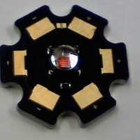
... Medical Automotive Description The LZ1-00R105 Red LED emitter provides 5W power in an extremely small package. With a 4.4mm x 4.4mm x 3.2mm ultra-small footprint, this package provides exceptional luminous flux density. The patent-pending design has unparalleled thermal and optical performance. The high quality materials used in the package are chosen to optimize light output and minimize stresses which results in monumental reliability and lumen maintenance ...
Page 2
... Typical Relative Spectral Power Distribution . . . . . . . . . . . . . . . . . . . . . . . . . . . . . . . . . 8 Typical Relative Dominant Wavelength Shift over Temperature . . . . . . . . . . . . . . . . . . 8 Typical Relative Light Output . . . . . . . . . . . . . . . . . . . . . . . . . . . . . . . . . . . . . . . . . . . . . 9 Typical Relative Light Output over Temperature . . . . . . . . . . . . . . . . . . . . . . . . . . . . . . 9 Typical Forward Current Characteristics . . . . . . . . . . . . . . . . . . . . . . . . . . . . . . . . . . . . 10 Current Derating Curves . . . . . . . . . . . . . . . . . . . . . . . . . . . . . . . . . . . . . . . . . . . . . . . . 10 Emitter Tape & Reel Specifications . . . . . . . . . . . . . . . . . . . . . . . . . . . . . . . . . . . . . . . . 11 Company Information . . . . . . . . . . . . . . . . . . . . . . . . . . . . . . . . . . . . . . . . . . . . . . . . . . 12 LedEngin, Inc. Table of Contents 2 LZ1-00R105 (01/14/10) ...
Page 3
... Lumen Maintenance at 100,000 hours of operation at a forward current of 1000 mA. This projection is based on constant current operation with junction temperature maintained at or below 110°C. LedEngin, Inc. Product Nomenclature Soak Requirements Standard Time (hrs) Conditions 168 85°C/ +5/-0 85 Accelerated Time (hrs) Conditions n/a n/a LZ1-00R105 (01/14/10) ...
Page 4
... Forward Voltage Bins Table 4: Minimum ) Forward Voltage ( 1000mA F (V) 2.24 2.48 2.72 2.96 3.20 4 Typical ) Luminous Flux (Φ [ 1500mA F (lm) 150 175 220 Maximum ) D [1,2] = 1000mA F (nm) 630 Maximum ) F [ 1000mA F (V) 2.48 2.72 2.96 3.20 3.44 LZ1-00R105 (01/14/10) ...
Page 5
... Solder conditions per JEDEC 020D. See Reflow Soldering Profile Figure 3. 5. Autoclave Conditions per JEDEC JESD22-A102-C. 6. LedEngin recommends taking reasonable precautions towards possible ESD damages and handling the LZ1-00R105 in an electrostatic protected area (EPA). An EPA may be adequately protected by ESD controls as outlined in ANSI/ESD S6.1. Optical Characteristics @ T ...
Page 6
... Figure 4: Recommended solder mask opening (hatched area) for anode, cathode, and thermal pad. Note for Figure 4: 1. Unless otherwise noted, the tolerance = ± 0.20 mm. LedEngin, Inc. Figure 3: Package outline drawing. 6 Pin Out Pad Function 1 Cathode 2 Anode 3 Anode 4 Cathode [2] 5 Thermal 1 4 3 LZ1-10R105 and LZ1-30R105 LZ1-00R105 (01/14/10) ...
Page 7
... Figure 3: Reflow soldering profile for lead free soldering. 100 -90 -80 -70 -60 -50 -40 -30 -20 - Figure 4: Typical representative spatial radiation pattern. LedEngin, Inc. Reflow Soldering Profile Typical Radiation Pattern Angular Displacement (Degrees) 7 LZ1-00R105 (01/14/10) ...
Page 8
... Figure 5: Relative spectral power vs. wavelength @ T Typical Relative Dominant Wavelength Shift over Temperature Figure 6: Typical relative dominant wavelength shift vs. case temperature. LedEngin, Inc. 500 550 600 Wavelength (nm) = 25° Case Temperature (ºC) 8 650 700 100 125 LZ1-00R105 (01/14/10) ...
Page 9
... Figure 7: Typical relative light output vs. forward current @ T Typical Relative Light Output over Temperature 120 100 Figure 8: Typical relative light output vs. case temperature. LedEngin, Inc. 400 600 800 1000 I - Forward Current (mA Case Temperature (°C) 9 1200 1400 1600 = 25°C. C 100 125 LZ1-00R105 (01/14/10) ...
Page 10
... Ambient Thermal Resistance] = RΘ J-A LedEngin, Inc. 2.2 2 Forward Voltage (V) F Current Derating RΘ = 9°C/W J-A RΘ = 12°C/W J-A RΘ = 15°C/W J Maximum Ambient Temperature (ºC) + RΘ [Case to Ambient Thermal Resistance]. J-C C-A 10 2.6 2 25°C. C 100 125 = 125°C. J(MAX) LZ1-00R105 (01/14/10) ...
Page 11
... Emitter Tape and Reel Specifications (mm) Figure 11: Emitter carrier tape specifications (mm). LedEngin, Inc. Figure 12: Emitter reel specifications (mm). 11 LZ1-00R105 (01/14/10) ...
Page 12
... LedEngin is committed to providing products that conserve natural resources and reduce greenhouse emissions. LedEngin reserves the right to make changes to improve performance without notice. Please contact Sales@ledengin.com LedEngin, Inc. Company Information or (408) 492-0620 for more information. 12 LZ1-00R105 (01/14/10) ...