E3Z-LS61 Omron, E3Z-LS61 Datasheet - Page 4
E3Z-LS61
Manufacturer Part Number
E3Z-LS61
Description
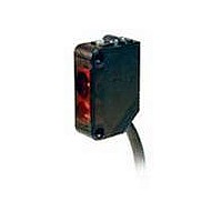
Industrial Photoelectric Sensors BGS/FGS NPN Output Diffuse pre-wired
Manufacturer
Omron
Type
Photoelectric Sensorsr
Series
E3Zr
Specifications of E3Z-LS61
Features
Adjustable sensing distance
Output
NPN
Sensing Method
Diffuse Reflective
Sensing Distance
20 mm to 200 mm
Light Source
Red LED
Connection
Prewired Cable
Output Configuration
NPN
Sensing Range
20mm To 200mm
Output Current
100mA
Sensor Output
NPN
Supply Voltage Range Dc
12V To 24V
Output Type
Transistor
Sensor Input
Optical
Supply Voltage Max
24VDC
Sensing Range Max
200mm
Sensing Object
White Paper
Sensing Light
Red
Mounting Type
Bracket Mount
Current - Supply
30mA
Voltage - Supply
12 V ~ 24 V
Package / Case
Module, Pre-Wired
Lead Free Status / RoHS Status
Lead free / RoHS Compliant
Lead Free Status / RoHS Status
Lead free / RoHS Compliant, Lead free / RoHS Compliant
Available stocks
Company
Part Number
Manufacturer
Quantity
Price
Company:

Part Number:
E3Z-LS61
Manufacturer:
OMRON
Quantity:
1 000
Company:
Part Number:
E3Z-LS61
Manufacturer:
OMRON
Quantity:
384


Principle of Operation
■ Background Suppression
Background Suppression: Objects beyond the set distance will not
be detected.
To ensure reliable background suppression, a minimum separation
distance between the set distance and the background is recom-
mended. Please refer to the “Hysteresis vs. Sensing Distance” graph
in the Engineering section of this data sheet to determine the mini-
mum separation distance.
Example: A target that has a reflectivity that is similar to a black
paper is set to a maximum set distance of 160 mm. Based on the
“Hysteresis vs. Sensing Distance” graph, the hysteresis is 5%. The
recommended minimum separation distance in this case is 8.0 mm
(5% of 160 mm) between the background and the set distance. This
means that the background must be at least 8.0 mm behind the set
distance.
■ Foreground Suppression
Foreground suppression: Objects in front of the set distance will
not be detected.
Objects with glossy or irregular surface often reflect the light emitted
from the sensor in different directions. This phenomenon often leads
to false detection. For such objects, a foreground suppression sensor
(FGS) or a polarized retro-reflective sensor is the sensor of choice.
For applications that do not have space for a reflector, the FGS is
ideal.
FGS sensors accomplish reliable detection by not detecting the
object directly. An FGS sensor uses a background, as a retro-reflec-
tive sensor would use a reflector, to reliably detect any object that
passes between itself and the background. FGS uses the position on
which the light reflected from the background strikes its receiver as a
point of reference (see the diagram at right.) A change in switching
state occurs when the light strikes the receiver at a different position.
Any object that passes between the sensor and the background will
reflect the light onto the receiver in a position that will be different
from the point of reference (reflection from the background).
To ensure reliable foreground suppression, a minimum separation
distance between the set distance and the background as well as a
minimum separation distance from the target to the set distance is
recommended. Please refer to the “Hysteresis vs. Sensing Distance”
graph in the Engineering section of this data sheet to determine the
minimum separation distance.
4
Distance-settable Photoelectric Sensor
E3Z-LS
Background Suppression Optical Configuration
Example: A target that has a reflectivity that is similar to a black
paper is set to a maximum set distance of 160 mm. Based on the
“Hysteresis vs. Sensing Distance” graph, the hysteresis is 5%. The
recommended minimum separation distance in this case is 8.0 mm
(5% of 160 mm) between the background and the set distance, and
8.0 mm between the set distance and the background. This means
that the background must be at least 8.0 mm behind the set distance,
and the set distance must be at least 8.0 mm behind the target.
Foreground Suppression Optical Configuration
Emitter
Emitter
Near
Near
Far
Far
Emitting Lens
Emitting Lens
Receiving
Receiving
Lens
Lens
160 mm
Target A
Target A
Separation
Distance
8 mm
Set Distance
Separation
Separation
8 mm
8 mm
Distance
Set Distance
Distance
Background
Background
Related parts for E3Z-LS61
Image
Part Number
Description
Manufacturer
Datasheet
Request
R

Part Number:
Description:
EMITTER ONLY FOR E3Z-T61
Manufacturer:
Omron
Datasheet:

Part Number:
Description:
Sensor; NPN/PNP; Photoelectric; 100 mm to 4 m; Red; 12 to 24 VDC 10 %; ABS
Manufacturer:
Omron Automation
Datasheet:
Part Number:
Description:
Sensor; PNP; Polarized Retroreflective Sensing Mode; Photoelectric; 30 mA; 1 ms
Manufacturer:
Omron Automation
Datasheet:

Part Number:
Description:
Photoelectric Sensors - Industrial Emitter Only for E3Z -T81
Manufacturer:
Omron
Datasheet:
Part Number:
Description:
LaserType TB,emit Only M12 NPN
Manufacturer:
Omron
Datasheet:
Part Number:
Description:
Thru Beam Sensor
Manufacturer:
Omron
Datasheet:
Part Number:
Description:
Cable
Manufacturer:
Omron
Datasheet:
Part Number:
Description:
Industrial Photoelectric Sensors NPN DIFF REFLECTIVE
Manufacturer:
Omron
Datasheet:

Part Number:
Description:
Industrial Photoelectric Sensors BGS/FGS NPN Output Diffuse M8 Connector
Manufacturer:
Omron
Datasheet:
Part Number:
Description:
G6S-2GLow Signal Relay
Manufacturer:
Omron Corporation
Datasheet:
Part Number:
Description:
Compact, Low-cost, SSR Switching 5 to 20 A
Manufacturer:
Omron Corporation
Datasheet:
Part Number:
Description:
Manufacturer:
Omron Corporation
Datasheet: