LH1522AB Vishay, LH1522AB Datasheet - Page 2
LH1522AB
Manufacturer Part Number
LH1522AB
Description
Solid State Relays Normally Open Dual Form 1A
Manufacturer
Vishay
Datasheet
1.LH1522AB.pdf
(7 pages)
Specifications of LH1522AB
Load Voltage Rating
200 V
Load Current Rating
0.2 A
Contact Form
2 Form A
Output Device
MOSFET
Case Color
Black
Maximum Operating Temperature
+ 85 C
Minimum Operating Temperature
- 40 C
Relay Type
Solid State
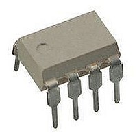
Package / Case
PDIP-8
Output Type
AC or DC
Termination Style
Solder Pin
Load Voltage Max
200V
Load Current
120mA
On State Resistance Max
15ohm
Contact Configuration
SPST-NO
Isolation Voltage
5300V
Forward Current If
1mA
Relay Terminals
Through Hole
Mounting Style
Through Hole
Lead Free Status / RoHS Status
Lead free / RoHS Compliant
Lead Free Status / RoHS Status
Lead free / RoHS Compliant, Lead free / RoHS Compliant
Available stocks
Company
Part Number
Manufacturer
Quantity
Price
Company:

Part Number:
LH1522AB
Manufacturer:
SIEMENS
Quantity:
5 510
Company:
Part Number:
LH1522AB
Manufacturer:
NCR
Quantity:
5 510


LH1522AB, LH1522AAC, LH1522AACTR
Vishay Semiconductors
Notes
•
(1)
(2)
(3)
Note
•
www.vishay.com
2
THE PRODUCT DESCRIBED HEREIN AND THIS DATASHEET ARE SUBJECT TO SPECIFIC DISCLAIMERS, SET FORTH AT
ABSOLUTE MAXIMUM RATINGS (T
PARAMETER
INPUT
LED continuous forward current
LED reverse voltage
OUTPUT
DC or peak AC load voltage
Continuous DC load current,
one pole operating
Continuous DC load current,
two poles operating
Peak load current (single shot)
SSR
Ambient temperature range
Storage temperature range
Pin soldering temperature
Input to output isolation test voltage
Pole-to-pole isolation voltage (S1 to S2)
(dry air, dust free, at sea level)
Output power dissipation (continuous)
ELECTRICAL CHARACTERISTICS (T
PARAMETER
INPUT
LED forward current, switch turn-on
LED forward current, switch turn-off
LED forward voltage
OUTPUT
On-resistance
Off-resistance
Current limit
Off-state leakage current
Output capacitance
Pole-to-pole capacitance (S1 to S2)
Switch offset
TRANSFER
Capacitance (input to output)
SWITCHING CHARACTERISTICS (T
PARAMETER
Turn-on time
Turn-off time
Stresses in excess of the absolute maximum ratings can cause permanent damage to the device. Functional operation of the device is not implied at these or
any other conditions in excess of those given in the operational sections of this document. Exposure to absolute maximum ratings for extended periods of the
time can adversely affect reliability.
Breakdown occurs between the output pins external to the package.
Refer to current limit performance application note 58 for a discussion on relay operation during transient currents.
Refer to reflow profile for soldering conditions for surface mounted devices (SMD). Refer to wave profile for soldering conditions for through hole devices (DIP).
Minimum and maximum values are testing requirements. Typical values are characteristics of the device and are the result of engineering evaluations. Typical
values are for information only and are not part of the testing requirements.
(3)
For technical questions, contact:
(1)
,
I
Dual 1 Form A Solid State Relay
F
This datasheet is subject to change without notice.
= 5 mA, t = 5 ms, V
I
I
I
I
I
I
F
F
F
t = 1 s, I
L
I
F
F
amb
amb
F
I
TEST CONDITION
TEST CONDITION
= 0 mA, V
= 0 mA, V
= 0 mA, V
I
F
= 100 mA, t = 10 ms
= 10 mA, I
= 10 mA, I
F
amb
= 5 mA, I
TEST CONDITION
= 0 mA, V
= 0 mA, V
V
I
= 25 °C, unless otherwise specified)
= 25 °C, unless otherwise specified)
t = 10 s max.
L
V
F
I
I
F
F
t = 100 ms
ISO
= 25 °C, unless otherwise specified)
I
I
= ± 150 V
= 10 mA
R
L
ISO
= 5 mA
= 5 mA
50 μA
10 μA
= 1 V
L
L
L
L
= 10 μA max.
L
L
= ± 100 V
= ± 100 V
= ± 200 V
L
= 50 mA
L
= 50 mA
= 50 mA
= 50 V
= 1 V
L
= ± 5 V
optocoupleranswers@vishay.com
SYMBOL
SYMBOL
R
R
I
I
V
I
C
LMT
C
C
t
t
Fon
Foff
V
I
I
SYMBOL
OFF
OS
on
off
ON
O
O
IO
F
O
O
T
P
V
T
T
V
V
amb
I
diss
I
I
I
ISO
stg
sld
F
L
L
P
R
L
MIN.
MIN.
1.15
300
0.2
0.5
6
- 40 to + 150
- 40 to + 85
VALUE
5300
1600
TYP.
5000
TYP.
1.26
0.02
0.15
200
200
140
260
600
360
1.1
0.5
1.1
0.7
50
10
60
15
(2)
8
1
1
www.vishay.com/doc?91000
Document Number: 83821
MAX.
MAX.
1.45
460
200
15
Rev. 1.6, 17-Mar-11
2
1
2
2
UNIT
V
mW
mA
mA
mA
°C
°C
°C
RMS
V
V
V
UNIT
UNIT
G
mA
mA
mA
ms
nA
μA
ms
pF
pF
pF
μV
pF
V
Related parts for LH1522AB
Image
Part Number
Description
Manufacturer
Datasheet
Request
R

Part Number:
Description:
Dual 1 Form A Solid State Relay
Manufacturer:
Vishay
Datasheet:
Part Number:
Description:
357-036-542-201 CARDEDGE 36POS DL .156 BLK LOPRO
Manufacturer:
Vishay
Datasheet:
Part Number:
Description:
357-036-542-201 CARDEDGE 36POS DL .156 BLK LOPRO
Manufacturer:
Vishay
Datasheet:
Part Number:
Description:
357-036-542-201 CARDEDGE 36POS DL .156 BLK LOPRO
Manufacturer:
Vishay
Datasheet:
Part Number:
Description:
357-036-542-201 CARDEDGE 36POS DL .156 BLK LOPRO
Manufacturer:
Vishay
Datasheet:
Part Number:
Description:
357-036-542-201 CARDEDGE 36POS DL .156 BLK LOPRO
Manufacturer:
Vishay
Datasheet:
Part Number:
Description:
357-036-542-201 CARDEDGE 36POS DL .156 BLK LOPRO
Manufacturer:
Vishay
Datasheet:
Part Number:
Description:
357-036-542-201 CARDEDGE 36POS DL .156 BLK LOPRO
Manufacturer:
Vishay
Datasheet:
Part Number:
Description:
357-036-542-201 CARDEDGE 36POS DL .156 BLK LOPRO
Manufacturer:
Vishay
Datasheet:
Part Number:
Description:
357-036-542-201 CARDEDGE 36POS DL .156 BLK LOPRO
Manufacturer:
Vishay
Datasheet:
Part Number:
Description:
357-036-542-201 CARDEDGE 36POS DL .156 BLK LOPRO
Manufacturer:
Vishay
Datasheet:
Part Number:
Description:
357-036-542-201 CARDEDGE 36POS DL .156 BLK LOPRO
Manufacturer:
Vishay
Datasheet:
Part Number:
Description:
357-036-542-201 CARDEDGE 36POS DL .156 BLK LOPRO
Manufacturer:
Vishay
Datasheet:
Part Number:
Description:
357-036-542-201 CARDEDGE 36POS DL .156 BLK LOPRO
Manufacturer:
Vishay
Datasheet:
Part Number:
Description:
357-036-542-201 CARDEDGE 36POS DL .156 BLK LOPRO
Manufacturer:
Vishay
Datasheet: