TCDT1110 Vishay, TCDT1110 Datasheet
TCDT1110
Specifications of TCDT1110
Available stocks


Related parts for TCDT1110

TCDT1110 Summary of contents
Page 1
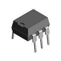
... Switch-mode power supplies Line receiver Computer peripheral interface Microprocessor system interface Description The TCDT1110/ TCDT1110G consists of a pho- totransistor optically coupled to a gallium arsenide infrared-emitting diode in a 6-PIN plastic dual inline package. Document Number 83531 Rev. 1.7, 26-Oct-04 ...
Page 2
... TCDT1110/ TCDT1110G Vishay Semiconductors Absolute Maximum Ratings °C, unless otherwise specified amb Stresses in excess of the absolute Maximum Ratings can cause permanent damage to the device. Functional operation of the device is not implied at these or any other conditions in excess of those given in the operational sections of this document. Exposure to absolute Maximum Rating for extended periods of the time can adversely affect reliability ...
Page 3
... Routine test Partial discharge test voltage - Lot test (sample test) (see figure 2) Insulation resistance V = 500 500 500 (construction test only) Document Number 83531 Rev. 1.7, 26-Oct-04 TCDT1110/ TCDT1110G Test condition Symbol = 0 CEsat = 1 Ω mA Test condition Symbol = 10 mA CTR F Test condition ...
Page 4
... TCDT1110/ TCDT1110G Vishay Semiconductors 300 P si (mW) 250 200 150 100 I si (mA 100 125 150 175 200 T ( ° 10934 amb Figure 1. Derating diagram Switching Characteristics Parameter Turn-off time 100 Ω (see figure Turn-on time 100 Ω (see figure Turn-off time (see figure 4) ...
Page 5
... V - Forward Voltage ( 11862 F Figure 7. Forward Current vs. Forward Voltage Document Number 83531 Rev. 1.7, 26-Oct-04 TCDT1110/ TCDT1110G 96 11698 t t storage time fall time turn-off time 1 1.3 1.2 1 ...
Page 6
... TCDT1110/ TCDT1110G Vishay Semiconductors 100.00 V =10V CE 10.00 1.00 0.10 0.01 0.1 1.0 10.0 I – Forward Current ( 11904 F Figure 10. Collector Current vs. Forward Current 100 20mA I =50mA F 10mA 10 5mA 2mA 1 1mA 0.1 0 – Collector Emitter Voltage ( 10985 CE Figure 11. Collector Current vs. Collector Emitter Voltage 1 ...
Page 7
... Customer Code/ Identification/ Option Logo V XXXY 68 Vishay Logo Date Code (year, week) 17936 Package Dimensions in mm Document Number 83531 Rev. 1.7, 26-Oct-04 TCDT1110/ TCDT1110G Product Code VDE Logo Plant Code Package Code Vishay Semiconductors Figure 16. Marking example www.vishay.com 7 ...
Page 8
... TCDT1110/ TCDT1110G Vishay Semiconductors Package Dimensions in mm www.vishay.com 8 14771 Document Number 83531 Rev. 1.7, 26-Oct-04 ...
Page 9
... Vishay Semiconductor GmbH, P.O.B. 3535, D-74025 Heilbronn, Germany Telephone: 49 (0)7131 67 2831, Fax number: 49 (0)7131 67 2423 Document Number 83531 Rev. 1.7, 26-Oct-04 TCDT1110/ TCDT1110G and may do so without further notice. Vishay Semiconductors www.vishay.com 9 ...
Page 10
... Information contained herein is intended to provide a product description only. No license, express or implied, by estoppel or otherwise, to any intellectual property rights is granted by this document. Except as provided in Vishay's terms and conditions of sale for such products, Vishay assumes no liability whatsoever, and disclaims any express or implied warranty, relating to sale and/or use of Vishay products including liability or warranties relating to fitness for a particular purpose, merchantability, or infringement of any patent, copyright, or other intellectual property right ...