VERSAKIT-30XX Ramtron, VERSAKIT-30XX Datasheet
VERSAKIT-30XX
Specifications of VERSAKIT-30XX


Related parts for VERSAKIT-30XX


VERSAKIT-30XX Summary of contents
Page 1
... Versa Ware JTAG software The user guide provides a complete description of the VersaKit-30xx feature set, as well as the development board schematics. The Versa Ware JTAG Software provides an easy-to-use platform for device programming and in-circuit debugging of the code. Include files and demonstration programs for the VRS51L3074 can be downloaded from the abovementioned web page ...
Page 2
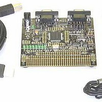
... VersaKit-30xx 3 Overview: VersaKit-30xx Development Board and the VJTAG Interface The figure below presents an overview of the VersaKit-30xx development board and its principal features: The VJTAG-USB board is a USB-based JTAG interface that enables in-circuit programming and debugging of the Ramtron VRS51L3074 and other JTAG-based MCUs. ...
Page 3
... VersaKit-30xx 4 Basic Development Board and VJTAG Setup The setup of the VersaKit-30xx is quick and easy. However, the order in which the operations are performed is important and should be followed. First, insert the VJTAG-USB into Header H2 on the devboard so that the CN1, USB connector sits directly on top of the devboard’ ...
Page 4
... VersaKit-30xx 5 Overview: Versa Ware JTAG Software Versa Ware JTAG is a Windows®-based software tool that provides a user-friendly development platform for all Ramtron microcontrollers featuring a JTAG interface (the VRS51L2xxx, VRS51L3xxx and future derivatives). The Versa Ware JTAG Software is composed of two parts: ...
Page 5
... VersaKit-30xx 6 Installing and Using the Versa Ware JTAG Software Installation of the Versa Ware JTAG Software is handled automatically by the set up program, which installs the: • Versa Ware JTAG Software • Prolific PL2303X USB driver As is the case with most software/driver installations, we recommend creating a system restore point before running the setup ...
Page 6
... VersaKit-30xx To download a HEX file into the VRS51L3074: 1. Make sure that the Versa-JTAG interface is properly connected to the H2 header of the devboard. 2. Click on the Synchronize 3. Click Open to select the HEX file to be programmed into the VRS51L3074. 4. Click on Erase then Program program will start. The Synchronize button can be used to halt execution of the VRS51L3074 program and put the device into program mode ...
Page 7
... VersaKit-30xx 6.2 Using the Versa Ware JTAG Debugger Once the program is loaded into the VRS51L3074 Flash memory and the debugger is enabled, activate the debugger by clicking the Debugger button. Upon startup, the debugger will halt the processor at address 0x0000 and wait. Once the debugger has started, either run the program at full speed by clicking on the Run anywhere in the code by either double clicking on a specific code line and then clicking the Run breakpoint manually ...
Page 8
... VersaKit-30xx When a breakpoint is set in the code, the breakpoint reference number will be displayed in red next to the code line. The breakpoint toolbar will then display the active breakpoint. Double clicking again on a given code line where a breakpoint has been set will disable that breakpoint. ...
Page 9
... VersaKit-30xx Once a breakpoint is reached, you can either: • Restart the program by clicking again on the Run • Single step through the code by clicking on the Step • View/edit SFR, IRAM, XRAM memory locations by clicking on SFR When the Step button is clicked, the processor will execute the current instruction and step to the next instruction (and actually stop) ...