EBWT11-A Bluegiga Technologies, EBWT11-A Datasheet
EBWT11-A
Specifications of EBWT11-A


Related parts for EBWT11-A


EBWT11-A Summary of contents
Page 1
WT11 Evaluation Kit ...
Page 2
... Copyright © 2000-2006 Bluegiga Technologies All rights reserved. Bluegiga Technologies assumes no responsibility for any errors, which may appear in this manual. Furthermore, Bluegiga Technologies reserves the right to alter the hardware, software, and/or specifications detailed herein at any time without notice, and does not make any commitment to update the information contained herein. Bluegiga Technologies’ ...
Page 3
Contents: 1. Introduction .................................................................................................4 2. Physical outlook ...........................................................................................5 3. Schematics ...................................................................................................6 4. Assembly......................................................................................................6 5. Gerber ..........................................................................................................6 6. SPI (J1) interface.........................................................................................7 7. GPIO (J2) interface ......................................................................................8 8. PIO SELECT (J3) ...........................................................................................9 9. RESET (J4) ...................................................................................................9 10. DSR (J5).......................................................................................................9 11. Speaker JACK ...
Page 4
VERSION HISTORY Version: Author: 1.0 MS TERMS & ABBREVIATIONS Term or Abbreviation: ASCII Bluetooth DTE DTR GPIO iWRAP PCM SPI UART USB WRAP Explanation: American Standard Code for Information Interchange Set of technologies providing audio and data transfer over short- ...
Page 5
... A ARGET PPLICATIONS WT11 Evaluation Kit is meant for evaluation and development of WRAP THOR WT11 Bluetooth modules or prototyping and piloting Bluetooth systems utilized with WRAP THOR WT11 module. E LECTRICAL FUNCTIONALITY Please, refer the details of WT11 Bluetooth module from the latest respective data sheet ...
Page 6
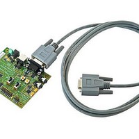
PHYSICAL OUTLOOK Figure 1: WT11 Evaluation Kit, Onboard Installation Kit and CD 5 ...
Page 7
SCHEMATICS Schematics of WT11 Evaluation Kit can be found from the CD delivered with the package or alternatively downloaded form www.bluegiga.com/techforum/. 4. ASSEMBLY Figure 2: WT11 Evaluation Kit assembly 5. GERBER Gerber of WT11 Evaluation Kit can be found ...
Page 8
SPI (J1) INTERFACE SPI interface pin configuration is show in Table 2. The physical interface is 2X3 pin header (AMP146134-2). PIN Name: No.: MISO 3.3 V CLK MOSI CSB GND Table 1: SPI Interface PIN description I/ ...
Page 9
GPIO (J2) INTERFACE General purpose interface pin configuration is show in 2X8 pin header (AMP146134-7). PIN Name: No.: RESET 3.3 V PIO2 PIO3 PIO4 PIO5 PIO6 PIO7 PCM_CLK PCM_OUT PCM_SYNC PCM_IN TxD RxD GND +V Table 2: GPIO interface ...
Page 10
PIO SELECT (J3) This switch toggles PIO2 to PIO7 signal connections between J2 connector and LED/USB/UART interfaces. Note: ‘Top’ and ‘bottom’ positions refer to viewing WT11 Evaluation Kit from top side as seen in Figure 2. • Top position ...
Page 11
SIG SELECT (J8) This switch toggles nCTS and RxD signals connection between J2 connector and DB9 RS232 connector. Note: ‘Top’ and ‘bottom’ positions refer to viewing WT11 Evaluation Kit from top side as seen in Figure 2. • Top ...
Page 12
USB (J10) INTERFACE J10 connector is a standard USB B receptacle connector. 16. POWER SUPPLY (J11) This connector is used with the 5V power supply delivered with the evaluation kit. Diameter 6.0mm, inner pin diameter 2.0mm. 17. POWER SUPPLY ...