CMD-HHCP-315-MD_ Linx Technologies Inc, CMD-HHCP-315-MD_ Datasheet - Page 2
CMD-HHCP-315-MD_
Manufacturer Part Number
CMD-HHCP-315-MD_
Description
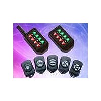
RF Modules & Development Tools 8 Btn Compact Hndhld TX 315MHz Snap Btns
Manufacturer
Linx Technologies Inc
Datasheet
1.CMD-HHCP-418.pdf
(5 pages)
Specifications of CMD-HHCP-315-MD_
Board Size
71.4 mm x 41.1 mm x 15.2 mm
Minimum Operating Temperature
- 40 C
Supply Voltage (min)
2.1 V
Product
RF Modules
Maximum Frequency
315 MHz
Supply Voltage (max)
3.6 V
Maximum Operating Temperature
+ 85 C
Lead Free Status / RoHS Status
Lead free / RoHS Compliant


Notes
1. Characterized, but not tested
THEORY OF OPERATION
Page 2
ELECTRICAL SPECIFICATIONS
Parameter
POWER SUPPLY
Operating Voltage
Supply Current
Power-Down Current
TRANSMITTER SECTION
Transmit Frequency Range:
Center Frequency Accuracy
ENVIRONMENTAL
Operating Temperature Range
CMD-HHCP-315
CMD-HHCP-418
CMD-HHCP-433
The CMD-HHCP-*** Compact Handheld transmitter combines the LR Series
transmitter with an internal Splatch Series antenna and an on-board Holtek
HT640 encoder IC to form a simple, yet highly reliable, RF remote control
transmitter. The LR transmitter is a low-cost, high-performance, synthesized
ASK / OOK transmitter. The transmitter’s synthesized architecture delivers
outstanding stability and frequency accuracy while minimizing the effects of
antenna port loading and mismatching. This reduces or eliminates frequency
pulling, bit contraction, and other negative effects common to SAW-based
transmitter architectures, providing a significantly higher level of performance
and reliability.
When a button is pressed on the transmitter, power is applied to the internal
circuitry and the encoder IC is enabled. The encoder detects the logic states of
the address lines and button data lines. These states are formatted into a three-
word transmission cycle that continues until the button is released. The encoder
data is used to modulate the transmitter, which, through the antenna, conveys
the data into free space. On the receiver side, a decoder IC or custom
microcontroller is used to check the transmitter’s address bits against the
address settings of the receiving device. If a match is confirmed, the decoder’s
outputs are set to replicate the transmitter’s button states. These outputs can
then be used to activate external circuitry required by the application.
The transmitter is compatible with several Linx receiver products, including the
LR, KH2, LT, and OEM product families. For applications where range is critical,
the LR Series receiver is the best choice due to its outstanding sensitivity. When
the transmitter is combined with an LR Series receiver and the HT658 decoder
chip, ranges of up to 1,000 feet are possible. Applications operating over shorter
distances will also benefit from the increased link reliability and superior noise
immunity provided by the LR Series receiver.
Designation
V
I
I
PDN
F
CC
–
–
CC
C
Min.
2.1
-50
-40
–
–
–
–
–
Typical
433.92
315
418
3.0
3.4
5.0
–
–
Max.
+50
+85
3.6
–
–
–
–
–
Units
VDC
MHz
MHz
MHz
kHz
mA
nA
°C
Notes
–
–
1
–
–
–
–
1
SETTING THE TRANSMITTER ADDRESS
BUTTON ASSIGNMENTS
Figure 3: CMD-HHCP-*** Button Assignments
The Compact Handheld transmitter
allows the selection of one of 1,024
unique addresses. All transmitters are
supplied set to the same address. To
avoid contention with other units or to
create unique relationships, the address
can be changed. This is accomplished
using internal DIP switches as shown.
The switches are accessed by removing
the DIP switch access cover on the back
of the transmitter.
If the switch is on, the address line is
connected to ground, otherwise it is floating. The receiver’s address must match
exactly in order for the units to communicate. Application Note AN-00300
describes in detail how to set the address to match any of the receivers offered
by Linx. This note can be found in the Support section of the Linx website,
www.linxtechnologies.com.
This diagram illustrates the relationship between the button locations and
encoder data lines.
D7
D5
D3
D1
Figure 2: DIP Switch Assignments
D6
D4
D2
D0
A0 = 1
A1 = 2
A2 = 3
A3 = 4
A4 = 5
A5 = 6
A6 = 7
A7 = 8
A8 = 9
A9 = 10
OFF ON
Page 3
Related parts for CMD-HHCP-315-MD_
Image
Part Number
Description
Manufacturer
Datasheet
Request
R

Part Number:
Description:
XMITTER HANDHELD 418MHZ 8 BUTTON
Manufacturer:
Linx Technologies Inc
Datasheet:
Part Number:
Description:
XMITTER HANDHELD 433MHZ 8 BUTTON
Manufacturer:
Linx Technologies Inc
Datasheet:
Part Number:
Description:
XMITTER HANDHELD 418MHZ 8 BUTTON
Manufacturer:
Linx Technologies Inc
Datasheet:
Part Number:
Description:
XMITTER HANDHELD 433MHZ 8 BUTTON
Manufacturer:
Linx Technologies Inc
Datasheet:
Part Number:
Description:
XMITTER HANDHELD 315MHZ 8 BUTTON
Manufacturer:
Linx Technologies Inc
Datasheet:

Part Number:
Description:
XMITTER HANDHELD 315MHZ 8 BUTTON
Manufacturer:
Linx Technologies Inc
Datasheet:

Part Number:
Description:
RF Modules & Development Tools 8 Button Compact Handhld Trans 433MHz
Manufacturer:
Linx Technologies Inc
Datasheet:

Part Number:
Description:
HOLDER BATTERY 20MM COIN CR2032
Manufacturer:
Linx Technologies Inc
Datasheet:

Part Number:
Description:
CONN RPSMA BL CRJA-CPV 8.5" COAX
Manufacturer:
Linx Technologies Inc

Part Number:
Description:
CABLE RG174 RPSMA M/F 8.5"
Manufacturer:
Linx Technologies Inc

Part Number:
Description:
MODULE USB LOW SPEED
Manufacturer:
Linx Technologies Inc
Datasheet:

Part Number:
Description:
IC TRANSCODER MT BI-DIR 20-SSOP
Manufacturer:
Linx Technologies Inc
Datasheet:

Part Number:
Description:
IC ENCODER LOW SECURITY 8DIP
Manufacturer:
Linx Technologies Inc
Datasheet:

Part Number:
Description:
IC DECODER MS SERIES 20-SSOP
Manufacturer:
Linx Technologies Inc
Datasheet:
Part Number:
Description:
IC ENCODER MS SERIES 20-SSOP
Manufacturer:
Linx Technologies Inc
Datasheet: