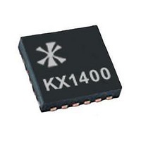
KX1400EG Keterex, KX1400EG Datasheet - Page 13

KX1400EG
Manufacturer Part Number
KX1400EG
Description
Audio D/A Converter ICs KX1400 Audio Playback IC
Manufacturer
Keterex
Datasheet
1.KX1400EW.pdf
(29 pages)
Specifications of KX1400EG
Resolution
12 bit
Operating Supply Voltage
2.7 V to 5.5 V
Operating Temperature Range
- 40 C to + 85 C
Maximum Power Dissipation
120 mW
Mounting Style
SMD/SMT
Number Of Dac Outputs
2
Power Consumption
320 mW
Supply Current
50 mA
Thd Plus Noise
40 dB
Package / Case
QFN-24
Lead Free Status / RoHS Status
Lead free / RoHS Compliant
entered, the KX1400 remains in pass-thru mode until a device reset occurs. See Section 8.1 for more
information on the Reset command.
In some applications, only one of the status signals (
When using the host MCU interface to control the KX1400, serial data flows in one direction only, from
the MCU to the KX1400. No serial data is returned from the KX1400. Two status signals (
KX1400 has completed execution of all pending commands from its buffer.
After
the host. Data from SDI is clocked into the shift register on each rising edge of the clock signal (SCL).
Data is sent most-significant-bit (MSB) first and must be transmitted as a complete 8-bit or 16-bit word.
After clocking all 8 or 16 bits into the shift register, a rising edge of
command buffer,
Pass-thru mode is entered by setting the Pass-thru Option Bit (Bit 5) of the Reset Command. Once
6.4. Host MCU Interface
The KX1400 provides an interface for transmitting audio data and control commands to the KX1400 from
an MCU host. The host MCU interface consists of five signals: three serial data signals output by the
MCU and two status signals generated by the KX1400.
the number of MCU I/O pins required. The three serial data signals are compatible with SPI
Microwire
Refer to Figure 6.4 and Table 6.5 for detailed timing information
6.4.1. Host MCU Interface Operation
BUSY) indicate the current state of the KX1400. The
accept the next data word from the host into its two-deep command buffer. BUSY is asserted when the
command buffer and initiate command execution (Figure 6.3). If space remains available in the two-deep
RDY
¯¯¯
SCL
SDI
CS
RDY
BUSY – Busy Status Signal, output from the KX1400
¯¯
¯¯¯
TM
is asserted by the KX1400, asserting
master controllers and support SPI mode 0 with a maximum clock rate approaching 4 MHz.
– Serial Data Clock, output from the MCU
– Serial Data Input, output from the MCU
– Chip Select (serial interface enable), output from the MCU
– Ready Status Signal, output from the KX1400
RDY
¯¯¯
will immediately be re-asserted and the next command transmission may begin.
Figure 6.3. MCU Host Interface Operation
CS
¯¯
enables an internal shift register to receive data from
RDY
¯¯¯
RDY
¯¯¯
or BUSY) may be necessary, thereby reducing
signal is asserted when the KX1400 is ready to
KX1400 Audio Playback IC
CS
¯¯
is required to latch the data into the
TM
and
RDY
¯¯¯
and
13


