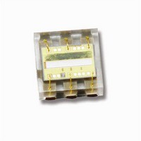
TSL2561T TAOS, TSL2561T Datasheet - Page 19

TSL2561T
Manufacturer Part Number
TSL2561T
Description
Light to Digital Converters Light to Digital with I2C
Manufacturer
TAOS
Specifications of TSL2561T
Maximum Operating Temperature
+ 70 C
Minimum Operating Temperature
- 30 C
Mounting Style
SMD/SMT
Package / Case
TMB
Response Time
400ms
Output Current
6mA
Supply Voltage Range Dc
2.7V To 3.6V
Supply Current
0.6mA
Operating Temperature Range
-30°C To +70°C
Operating Temperature Min
-30°C
Rohs Compliant
Yes
Operating Temperature Max
70°C
Sensor Output
I2C
Lead Free Status / RoHS Status
Lead free / RoHS Compliant
Available stocks
Company
Part Number
Manufacturer
Quantity
Price
Part Number:
TSL2561T
Manufacturer:
AMS
Quantity:
20 000
Basic Operation
// Read ADC Channels Using Read Word Protocol − RECOMMENDED
// Read ADC Channels Using Read Byte Protocol
The LUMENOLOGY r Company
After applying V
to access the CONTROL register followed by the data value 03h to power up the device. At this point, both ADC
channels will begin a conversion at the default integration time of 400 ms. After 400 ms, the conversion results
will be available in the DATA0 and DATA1 registers. Use the following pseudo code to read the data registers:
Address = 0x39
//Address the Ch0 lower data register and configure for Read Word
Command = 0xAC
//Reads two bytes from sequential registers 0x0C and 0x0D
//Results are returned in DataLow and DataHigh variables
ReadWord (Address, Command, DataLow, DataHigh)
Channel0 = 256 * DataHigh + DataLow
//Address the Ch1 lower data register and configure for Read Word
Command = 0xAE
//Reads two bytes from sequential registers 0x0E and 0x0F
//Results are returned in DataLow and DataHigh variables
ReadWord (Address, Command, DataLow, DataHigh)
Channel1 = 256 * DataHigh + DataLow
Address = 0x39
Command = 0x8C
ReadByte (Address, Command, DataLow)
Command = 0x8D
ReadByte (Address, Command, DataHigh)
Channel0 = 256 * DataHigh + DataLow
Command = 0x8E
ReadByte (Address, Command, DataLow)
Command = 0x8F
ReadByte (Address, Command, DataHigh)
Channel1 = 256 * DataHigh + DataLow
DD
, the device will initially be in the power-down state. To operate the device, issue a command
APPLICATION INFORMATION: SOFTWARE
r
www.taosinc.com
//Slave addr – also 0x29 or 0x49
//Set Command bit and Word bit
//Set bit fields 7 and 5
//Shift DataHigh to upper byte
//Slave addr − also 0x29 or 0x49
//Address the Ch0 lower data register
//Result returned in DataLow
//Address the Ch0 upper data register
//Result returned in DataHigh
//Shift DataHigh to upper byte
//Address the Ch1 lower data register
//Result returned in DataLow
//Address the Ch1 upper data register
//Result returned in DataHigh
//Shift DataHigh to upper byte
LIGHT-TO-DIGITAL CONVERTER
r
TSL2560, TSL2561
Copyright E 2009, TAOS Inc.
TAOS059N − MARCH 2009
19


