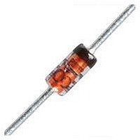
1N4148-TAP Vishay, 1N4148-TAP Datasheet - Page 2

1N4148-TAP
Manufacturer Part Number
1N4148-TAP
Description
Diodes (General Purpose, Power, Switching) vR/100V Io/150mA
Manufacturer
Vishay
Datasheet
1.1N4148TR.pdf
(4 pages)
Specifications of 1N4148-TAP
Product
Switching Diodes
Peak Reverse Voltage
100 V
Forward Continuous Current
0.3 A
Max Surge Current
2 A
Configuration
Single
Recovery Time
8 ns
Forward Voltage Drop
1 V
Maximum Reverse Leakage Current
0.025 uA
Operating Temperature Range
+ 175 C
Maximum Operating Temperature
+ 175 C
Minimum Operating Temperature
- 65 C
Mounting Style
Through Hole
Package / Case
DO-35-2
Diode Type
Switching
Forward Current If(av)
150mA
Repetitive Reverse Voltage Vrrm Max
100V
Forward Voltage Vf Max
1V
Reverse Recovery Time Trr Max
8ns
Forward Surge Current Ifsm Max
2A
Lead Free Status / RoHS Status
Lead free / RoHS Compliant
Lead Free Status / RoHS Status
Lead free / RoHS Compliant, Lead free / RoHS Compliant
Available stocks
Company
Part Number
Manufacturer
Quantity
Price
Company:
Part Number:
1N4148-TAP
Manufacturer:
VSS
Quantity:
180 000
Part Number:
1N4148-TAP
Manufacturer:
VISHAY/威世
Quantity:
20 000
1N4148
Vishay Semiconductors
Electrical Characteristics
T
Typical Characteristics
T
www.vishay.com
2
Forward voltage
Reverse current
Breakdown voltage
Diode capacitance
Rectification efficiency
Reverse recovery time
amb
amb
Figure 1. Forward Voltage vs. Junction Temperature
= 25 °C, unless otherwise specified
= 25 °C, unless otherwise specified
94 9169
94 9170
Figure 2. Forward Current vs. Forward Voltage
1000
Parameter
100
1.2
1.0
0.8
0.6
0.4
0.2
0.1
10
0
1
- 30
0
1N4148
T
0.4
j
0
- Junction Temperature (°C)
V
F
DiodesAmericas@vishay.com, DiodesAsia@vishay.com,
- Forward Voltage (V)
For technical questions within your region, please contact one of the following:
30
0.8
I
F
V
Scattering Limit
0.1 mA
R
= 100 mA
1.2
60
I
= 0, f = 1 MHz, V
F
i
I
R
V
R
V
= I
I
T
HF
F
R
= 0.1 x I
= 100 µA, t
J
R
= 10 mA, V
= 25 °C
= 20 V, T
Test condition
= 2 V, f = 100 MHz
= 10 mA, i
90
1.6
I
t
V
V
p
F
R
R
10 mA
= 0.3 ms
= 10 mA
1 m A
R
= 20 V
= 75 V
, R
120
j
p
2.0
= 150 °C
/T = 0.01,
L
R
R
= 100
HF
= 6 V,
= 1 mA
= 50 mV
Symbol
V
C
V
(BR)
I
I
I
t
t
R
R
R
rr
rr
F
D
r
Figure 3. Reverse Current vs. Reverse Voltage
94 9098
1000
100
10
DiodesEurope@vishay.com
1
1
Min.
100
T
45
Scattering Limit
j
= 25 °C
V
R
- Reverse Voltage (V)
Typ.
10
Document Number 81857
1000
Max.
25
50
5
4
8
4
Rev. 1.3, 29-Oct-10
100
Unit
mV
nA
µA
µA
pF
ns
ns
%
V


