SB340-E3/51 Vishay, SB340-E3/51 Datasheet

Schottky (Diodes & Rectifiers) 3.0 Amp 40 Volt

SB340-E3/51

Manufacturer Part Number
SB340-E3/51
Description
Schottky (Diodes & Rectifiers) 3.0 Amp 40 Volt
Manufacturer
Vishay
Datasheet

Specifications of SB340-E3/51

Product
Schottky Diodes
Peak Reverse Voltage
40 V
Forward Continuous Current
3 A
Max Surge Current
120 A
Configuration
Single
Forward Voltage Drop
0.49 V
Maximum Reverse Leakage Current
0.5 uA
Operating Temperature Range
- 65 C to + 125 C
Mounting Style
Through Hole
Package / Case
DO-201AD
Lead Free Status / RoHS Status
Lead free / RoHS Compliant
Note:
(1) Pulse test: 300 µs pulse width, 1 % duty cycle
Document Number: 88719
Revision: 20-Aug-07
PRIMARY CHARACTERISTICS
MAXIMUM RATINGS (T
PARAMETER
Maximum repetitive peak reverse voltage
Maximum RMS voltage
Maximum DC blocking voltage
Maximum average forward rectified current at
0.375" (9.5 mm) lead length (Fig. 1)
Peak forward surge current 8.3 ms single half
sine-wave superimposed on rated load
Operating junction temperature range
Storage temperature range
ELECTRICAL CHARACTERISTICS (T
PARAMETER
Maximum instantaneous forward voltage
Maximum instantaneous reverse current at
rated DC blocking voltage
T
V
I
J
I
F(AV)
FSM
RRM
V
max.
F
DO-201AD
(1)
A
= 25 °C unless otherwise noted)
(1)
125 °C, 150 °C
0.49 V, 0.68 V
Schottky Barrier Rectifier
20 V to 60 V
at 3.0 A
T
T
120 A
3.0 A
TEST CONDITIONS
A
A
= 25 °C
= 100 °C
SYMBOL
A
V
V
I
T
I
V
F(AV)
= 25 °C unless otherwise noted)
FSM
RRM
RMS
STG
T
DC
J
SB320
SYMBOL
20
14
20
FEATURES
TYPICAL APPLICATIONS
For use in low voltage high frequency inverters,
free-wheeling, dc-to-dc converters, and polarity
protection applications.
MECHANICAL DATA
Case: DO-201AD
Epoxy meets UL 94V-0 flammability rating
Terminals: Matte tin plated leads, solderable per
J-STD-002B and JESD22-B102D
E3 suffix for commercial grade
Polarity: Color band denotes the cathode end
V
I
• Guardring for overvoltage protection
• Very small conduction losses
• Extremely fast switching
• Low forward voltage drop
• High forward surge capability
• High frequency operation
• Solder dip 260 °C, 40 seconds
• Component in accordance to RoHS 2002/95/EC
R
F
and WEEE 2002/96/EC
- 65 to + 125
SB330
SB320
30
21
30
Vishay General Semiconductor
- 65 to + 150
SB330
0.49
SB340
20
120
3.0
40
28
40
SB340
SB320 thru SB360
0.5
SB350
50
35
50
- 65 to + 150
SB350
0.68
10
SB360
SB360
60
42
60
www.vishay.com
UNIT
UNIT
mA
°C
°C
V
V
V
V
A
A
1

Related parts for SB340-E3/51

SB340-E3/51 Summary of contents

Page 1

... F(AV) I FSM 125 J T STG = 25 °C unless otherwise noted) A TEST CONDITIONS SYMBOL SB320 ( ° 100 °C A SB320 thru SB360 Vishay General Semiconductor SB340 SB350 SB360 3.0 120 - 150 - 150 SB330 SB340 SB350 SB360 0.49 0.68 0 www.vishay.com UNIT °C °C UNIT ...

Page 2

... Pulse Width = 300 µ Duty Cycle °C J SB320 - SB340 SB350 & SB360 0.2 0.4 0.6 0.8 1.0 1.2 1.4 1.6 Instantaneous Forward Voltage ( 125 ° °C J SB320 - SB340 SB350 & SB360 100 Document Number: 88719 Revision: 20-Aug-07 UNIT °C/W ...

Page 3

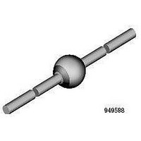
... SB320 - SB340 SB350 & SB360 10 0 Reverse Voltage (V) Figure 5. Typical Junction Capacitance PACKAGE OUTLINE DIMENSIONS in inches (millimeters) Document Number: 88719 Revision: 20-Aug-07 100 ° 1.0 MHz mVp-p sig 10 1 0.1 100 DO-201AD 1.0 (25.4) MIN. 0.210 (5.3) 0.190 (4.8) DIA ...

Page 4

... Information contained herein is intended to provide a product description only. No license, express or implied, by estoppel or otherwise, to any intellectual property rights is granted by this document. Except as provided in Vishay's terms and conditions of sale for such products, Vishay assumes no liability whatsoever, and disclaims any express or implied warranty, relating to sale and/or use of Vishay products including liability or warranties relating to fitness for a particular purpose, merchantability, or infringement of any patent, copyright, or other intellectual property right ...

Related keywords