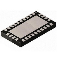
MAX2009ETI+ Maxim Integrated Products, MAX2009ETI+ Datasheet

MAX2009ETI+
Specifications of MAX2009ETI+
Related parts for MAX2009ETI+
MAX2009ETI+ Summary of contents
Page 1
... PCS1900 Base Stations Feed-Forward PA Architectures Digital Baseband Predistortion Architectures Military Applications WLAN Applications ________________________________________________________________ Maxim Integrated Products For pricing, delivery, and ordering information, please contact Maxim Direct at 1-888-629-4642, or visit Maxim's website at www.maxim-ic.com. 1200MHz to 2500MHz Adjustable ♦ 12dB ACPR Improvement* ♦ Independent Gain and Phase Expansion Controls ♦ ...
Page 2
Adjustable RF Predistorter ABSOLUTE MAXIMUM RATINGS GND ..............................................-0.3V to +5.5V CCG CCP ING, OUTG, GCS, GFS, GBP to GND......-0. INP, OUTP, PFS_, PDCS_, PBRAW, PBEXP, PBIN to GND ............................-0. ...
Page 3
AC ELECTRICAL CHARACTERISTICS (MAX2009 EV kit +4.75V to +5.25V, 50Ω environment, P CCG CCP V = +5.0V +1.2V GFS GBP PBIN are 2140MHz +5V, ...
Page 4
Adjustable RF Predistorter AC ELECTRICAL CHARACTERISTICS (continued) (MAX2009 EV kit +4.75V to +5.25V, 50Ω environment, P CCG CCP V = +5.0V +1.2V GFS GBP PBIN PDCS1 are at ...
Page 5
EV kit +5.0V -20dBm, V CCP IN unless otherwise noted.) SUPPLY CURRENT vs. SUPPLY VOLTAGE 6.3 6.2 6.1 6 +85° +25°C A 5.8 5 -40°C 5.6 A ...
Page 6
Adjustable RF Predistorter (MAX2009 EV kit +5.0V -20dBm, V CCP IN unless otherwise noted.) SMALL-SIGNAL GAIN vs. FREQUENCY -5.0 -5.5 -6 4.75V, 5.0V, 5.25V CCP -6.5 -7.0 -7.5 -8.0 -8.5 -9.0 ...
Page 7
EV kit +5.0V -20dBm, V CCP IN unless otherwise noted.) GAIN EXPANSION vs. INPUT POWER -6.0 -6.2 -6 -6.8 -7.0 -7 -7.4 -7 ...
Page 8
Adjustable RF Predistorter (MAX2009 EV kit +5.0V -20dBm, V CCP IN unless otherwise noted.) GAIN EXPANSION vs. INPUT POWER -5 5. 1.5V PDCS1 PF_S1 -5 -40°C A ...
Page 9
EV kit +5.0V -20dBm, V CCG IN otherwise noted.) LARGE-SIGNAL INPUT RETURN LOSS vs. FREQUENCY +15dBm 1.1 1.3 1.5 ...
Page 10
Adjustable RF Predistorter (MAX2009 EV kit +5.0V -20dBm, V CCG IN otherwise noted.) GROUP DELAY vs. FREQUENCY 0.75 0.70 D 0.65 0. 0.55 B 0.50 0.45 1.1 1.3 1.5 1.7 1.9 ...
Page 11
EV kit +5.0V -20dBm, V CCG IN otherwise noted.) GAIN EXPANSION vs. INPUT POWER - -11 - -15 D -17 -19 -21 - ...
Page 12
Adjustable RF Predistorter PIN NAME 10, 16, 20, GND Ground. Internally connected to the exposed paddle. 22, 26 Gain Input. Connect ING to a coupling capacitor ...
Page 13
Phase Expansion Circuitry Figure 1 shows a typical PA’s phase behavior with respect to input power. For input powers less than the breakpoint level, the phase remains relatively constant. As the input power becomes greater than the break- point level, ...
Page 14
Adjustable RF Predistorter PF_S1 Figure 2. Simplified Phase Slope Internal Circuitry PA GAIN COMPRESSION BREAKPOINT SLOPE P (dBm) IN Figure 3. PA Gain Compression Canceled by MAX2009 Gain Expansion 14 ______________________________________________________________________________________ PFS1 PHASE-CONTROL CIRCUITRY PFS2 2 PDCS1 ...
Page 15
Gain Expansion Breakpoint The gain expansion breakpoint is usually controlled by a DAC connected through the GBP pin. The GBP input voltage range of 0. corresponds to a breakpoint input power range of 3dBm to 23dBm. To achieve ...
Page 16
Adjustable RF Predistorter V = 1.5V PF_S1 Figure 4. AM-PM Response Tuning Circuit Power-Supply Bypassing Bypass each V pin with a 0.01µF capacitor. CC Exposed Pad RF The exposed paddle (EP) of the MAX2009’s ...
Page 17
PREAMPLIFIER 1.5V PF_S1 V = 0.8V PBIN PDCS1 PDCS2 Figure 5. MAX2009 Phase and Gain Optimization Circuit ______________________________________________________________________________________ 1200MHz to 2500MHz Adjustable PREAMPLIFIER GAIN = 7dB 6 3 OUTP ING ...
Page 18
Adjustable RF Predistorter mils 160 mils C6 C7 POWER AMPLIFER GND* OPTIONAL MATCH COMPENSATION* GND mils 160 mils C8 ING C9 GND* GND* C10 OUTP GND* PREAMPLIFER ...
Page 19
... Maxim cannot assume responsibility for use of any circuitry other than circuitry entirely embodied in a Maxim product. No circuit patent licenses are implied. Maxim reserves the right to change the circuitry and specifications without notice at any time. Maxim Integrated Products, 120 San Gabriel Drive, Sunnyvale, CA 94086 408-737-7600 ____________________ 19 © 2003 Maxim Integrated Products 1200MHz to 2500MHz Adjustable is a registered trademark of Maxim Integrated Products ...


