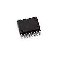
DG211BDY-E3 Vishay, DG211BDY-E3 Datasheet - Page 2

DG211BDY-E3
Manufacturer Part Number
DG211BDY-E3
Description
Analog Switch ICs Quad SPST Switch
Manufacturer
Vishay
Type
Analog Switchr
Specifications of DG211BDY-E3
Number Of Switches
Quad
Switch Configuration
SPST
On Resistance (max)
160 Ohms
On Time (max)
300 ns
Off Time (max)
200 ns
Supply Voltage (max)
25 V
Supply Voltage (min)
4.5 V
Maximum Power Dissipation
640 mW
Maximum Operating Temperature
+ 85 C
Mounting Style
SMD/SMT
Package / Case
SOIC-16 Narrow
Minimum Operating Temperature
- 40 C
Analogue Switch Type
SPST
No. Of Channels
4
On State Resistance Max
85ohm
Turn Off Time
200ns
Turn On Time
300ns
Supply Voltage Range
4.5V To 25V
Operating Temperature Range
-40°C To +85°C
Multiplexer Configuration
Quad SPST
Number Of Inputs
4
Number Of Outputs
4
Number Of Channels
4
Analog Switch On Resistance
160@12VOhm
Package Type
SOIC N
Power Supply Requirement
Single/Dual
Single Supply Voltage (min)
4.5V
Single Supply Voltage (typ)
5/9/12/15/18/24V
Single Supply Voltage (max)
25V
Dual Supply Voltage (min)
±4.5V
Dual Supply Voltage (typ)
±5/±9/±12/±15V
Dual Supply Voltage (max)
±22V
Power Dissipation
640mW
Mounting
Surface Mount
Pin Count
16
Operating Temp Range
-40C to 85C
Operating Temperature Classification
Industrial
Package
16SOIC N
Maximum On Resistance
160@12V Ohm
Maximum High Level Output Current
100 mA
Maximum Turn-off Time
200@±15V ns
Maximum Turn-on Time
300@±15V ns
Switch Architecture
SPST
Power Supply Type
Single|Dual
Lead Free Status / RoHS Status
Lead free / RoHS Compliant
Lead Free Status / RoHS Status
Lead free / RoHS Compliant, Lead free / RoHS Compliant
Available stocks
Company
Part Number
Manufacturer
Quantity
Price
DG211B/212B
Vishay Siliconix
Voltages Referenced to V–
V+
GND
Digital Inputs
Current, Any Terminal
Peak Current, S or D
(Pulsed at 1 ms, 10% duty cycle max)
Storage Temperature
www.vishay.com FaxBack 408-970-5600
4-2
. . . . . . . . . . . . . . . . . . . . . . . . . . . . . . . . . . . . . . . . . . . . . . . . . . . . . . . . . . .
. . . . . . . . . . . . . . . . . . . . . . . . . . . . . . . . . . . . . . . . . . . . . . . . . . . . . . . . .
GND
IN
V+
V–
V
X
L
a
V
S
, V
D
. . . . . . . . . . . . . . . . . . . . . . . . . .
. . . . . . . . . . . . . . . . . . . . . . . . . . . . . . . . . . . . . . . .
. . . . . . . . . . . . . . . . . . . . . . . . . . . . . . . . . .
Temp Range
. . . . . . . . . . . . . . . . . . . . . . . . .
–40 to 85 C
–40 to 85 C
40
40
or 30 mA, whichever occurs first
85 C
85 C
(V–) –2 V to (V+) +2 V
–65 to 125 C
100 mA
30 mA
16-Pin Narrow SOIC
16-Pin Narrow SOIC
16-Pin Plastic DIP
16-Pin Plastic DIP
44 V
25 V
16-Pin TSSOP
16-Pin TSSOP
FIGURE 1.
Package
Level
Shift/
Drive
Power Dissipation (Package)b
16-Pin Plastic DIP
16-Pin Narrow SOIC and TSSOP
Notes:
a.
b.
c.
d.
Signals on S
diodes. Limit forward diode current to maximum current ratings.
All leads welded or soldered to PC Board.
Derate 6.5 mW/ C above 75 C
Derate 7.6 mW/ C above 75 C
X
DG211BDJ
DG212BDJ
DG211BDY
DG212BDY
DG211BDQ
DG212BDQ
c
, D
Part Number
. . . . . . . . . . . . . . . . . . . . . . . . . . . . . . . . . . . . . . . . .
X
, or IN
X
exceeding V+ or V– will be clamped by internal
d
. . . . . . . . . . . . . . . . . . . . . . . . . . . .
S-00788—Rev. H, 24-Apr-00
Document Number: 70040
V–
V+
S
D
470 mW
640 mW
X
X


