UTS10DCG Souriau Connection Technology, UTS10DCG Datasheet - Page 31
UTS10DCG
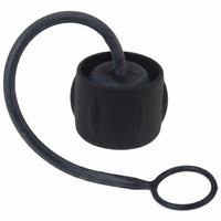
Manufacturer Part Number
UTS10DCG
Description
CONN RCPT SEALING CAP SIZE 10
Manufacturer
Souriau Connection Technology
Series
Trim Trio® UTSr
Specifications of UTS10DCG
Accessory Type
Cap (Cover), Sealing
Shell Size - Insert
10
Features
Metal Chain
Color
Black
Mil Type
MIL-DTL-26482 I
Product Type
Dustcaps
Shell Style
Receptacle
Shell Size
10
Mounting Style
Through Hole
Termination Style
Screw
Mounting Angle
Straight
Connector Shell Size
10
Connector Body Material
Plastic
Body Material
Plastic
Rohs Compliant
Yes
Lead Free Status / RoHS Status
Lead free / RoHS Compliant
For Use With/related Products
Trim Trio® UTS Receptacle
For Use With
SOU1525 - CONN RCPT JAM NUT 6POS W/SCKTSOU1524 - CONN RCPT JAM NUT 6POS W/PINSOU1290 - CONN RCPT 6X1.0 MALE JAM NUTSOU1289 - CONN RCPT 4X1.6 MALE JAM NUTSOU1288 - CONN RCPT 3X1.6 MALE JAM NUTSOU1281 - CONN RCPT 6X1.0 FEMALE JAM NUTSOU1280 - CONN RCPT 4X1.6 FEMALE JAM NUTSOU1279 - CONN RCPT 3X1.6 FEMALE JAM NUT
Lead Free Status / Rohs Status
Lead free / RoHS Compliant
Other names
SOU1315


<<
UTS Series
Solar radiation affects all materials, but plastics can be
susceptible to extreme degradation over time.
choice of materials for the UTS series was therefore a
critical consideration.
All over the world we are not exposed to the same
amount of energy given by the sun. The chart shown
here clearly illustrates this.
So we performed test according to the ISO 4892-2 and
simulated 5 years exposure to outdoor environments
(temperature, humidity, etc...)
After this period there was no significant colour variation,
no crazing, no cracking and no major variation of
mechanical properties.
One of the key factors which affects the performance of
a connector, is the way contacts are terminated. Crimped
connections are nowadays seen as the best solution to ensure
quality throughout the lifetime of the product. Here are some
reasons why we recommend this method of termination for UTS
connectors:
Advantages (Extract from the IEC 60352-2):
- Efficient processing of connections at each production level
- Processing by fully-automatic or semi- automatic crimping
- No cold-soldered joints
- No degradation of the spring characteristic of female contacts
- No health risk from heavy metal and flux steam
- Preservation of conductor flexibility behind the crimped
- No burnt, discolored and overheated wire insulation
- Good connections with reproducible electrical and mechanical
- Easy production control
SM24M1 -
SC24M1 -
SM20M1 -
SC20M1 -
SM1 6M1 -
machines, or with hand operated tools
by the soldering temperature
connection
performances
SC1 6M1 -
AWG
wire
28
26
24
22
20
18
16
Wire crimp
0.762 1.549 0.737 1.575
0.762 1.549 0.889 1.575
0.864 1.549 0.889 1.575 1.372 1.626
0.965 1.575 1.168 2.083 1.676 2.235
1.067 1.575 1.168 2.083 1.676 2.235
1.372 2.667
1.473
T
±0.076
W
2.68
±0.254
min
Ø wire
Insulation crimp
3.1 75
3.1 75
max
The
1.27
1.27
min
UV resistance
T
1.524
1.524
- 30°
- 60°
- 90°
max
90°
60°
30°
Crimping
- 180°
0°
60
- 1 50°
Yearly mean of daily irradiation in UV (280-400 nm)
To ensure that the crimp tooling is performing according to
original specifications, it is important to carry out regular checks.
A common way to check the performance of tooling is with a
simple pull test, ideally using a dedicated electric pull tester.
Minimum recommended full forces are indicated in the tables
below:
- 1 20°
MM²
0.05
0.08
0.22
0.25
0.32
0.82
0.1 2
0.1 4
0.75
cross-section
0.5
1.0
Conductor
on horizontal plane (J/cm²) (1990-2004)
- 90°
W
- 60°
AWG
30
28
26
24
22
20
18
- 30°
Pull out
force
108
18
28
32
40
60
85
90
1 1
1 5
N
6
0°
30°
MM²
10.0
cross-section
1.3
1.5
2.1
2.5
3.3
4.0
5.3
6.0
8.4
60°
Conductor
90°
W
AWG
16
10
1 4
1 2
8
1 20°
1 50°
Pull out
force
200
230
275
310
355
360
370
380
1 35
1 50
N
180°
J/cm²
UTS Series
There are two main standards for industrial connectors: UL94 & UL1 977
UL94
This standard is dedicated to plastics flammability. It characterises how the material burns in various orientation and thicknesses.
The UTS series has been rated at V-0 & HB.
Procedure: A specimen is supported in a vertical or horizontal position and a flame is applied to the bottom of the specimen. The flame is
applied for ten seconds and then removed until flaming stops, at which time the flame is reapplied for another ten seconds and then removed.
Two sets of five specimens are tested. The two sets are conditioned under different conditions.
V-0 Vertical burning:
• Specimens must not burn with flaming combustion for more
• Total flaming combustion time must not exceed 50 seconds
• Specimens must not burn with flaming or glowing combustion
• Specimens must not drip flaming particles that ignite the
• No specimen can have glowing combustion remain for longer
HB Horizontal burning:
• A material classed HB shall not have a burning rate exceeding
• A material classed HB shall not have a burning rate exceeding
• A material classed HB shall cease to burn before the 100 mm
than 10 seconds after either test flame application.
for each set of 5 specimens.
up to the specimen holding clamp.
cotton.
than 30 seconds after removal of the test flame.
40 mm per minute over a 75 mm span for specimens having
a thickness of 3.0 to 1 3 mm.
75 mm per minute over a 75 mm span for specimens having
a thickness less than 3.0 mm.
reference mark.
Underwriter Laboratories
61
1 2’’
5’’
Wire gauze
~ ~
1 00
25
±1
±1
45°
mm
mm
Cotton
45°
Material
Wire gauze
1 0
±1
45°
mm
>>
Related parts for UTS10DCG
Image
Part Number
Description
Manufacturer
Datasheet
Request
R

Part Number:
Description:
CONN SEALING FOR WALL RCPT #22
Manufacturer:
Souriau Connection Technology
Part Number:
Description:
CONN SEALING FOR WALL RCPT #14
Manufacturer:
Souriau Connection Technology
Datasheet:

Part Number:
Description:
CONN RCPT SEALING CAP SIZE 14
Manufacturer:
Souriau Connection Technology
Datasheet:

Part Number:
Description:
CONN STRAIN RELIEF 12POS
Manufacturer:
Souriau Connection Technology
Datasheet:

Part Number:
Description:
CONN PLUG SEALING CAP SIZE 12
Manufacturer:
Souriau Connection Technology
Datasheet:

Part Number:
Description:
D38999 Series 3
Manufacturer:
Souriau Connection Technology
Datasheet: