AF1-B0-34-625-1G1-C Carling Technologies, AF1-B0-34-625-1G1-C Datasheet - Page 4
AF1-B0-34-625-1G1-C
Manufacturer Part Number
AF1-B0-34-625-1G1-C
Description
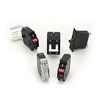
Circuit Breakers 25 A ONE POLE
Manufacturer
Carling Technologies
Series
Ar
Datasheet
1.AC1-B0-34-610-1G1-C.pdf
(23 pages)
Specifications of AF1-B0-34-625-1G1-C
Product Type
Circuit Breakers
Current Rating
25 Amps
Voltage Rating
277 VoltsAC / 80 VoltsDC
Trip Time
0.6 s to 20 s
Mounting Style
Screw
Termination Style
Screw
Circuit Function
Series Trip (Current)
Color
White
Dielectric Strength
1.5 KV
Features
A rockerguard and push-to-reset bezel help prevent inadvertent actuation
Illuminated
No
Length
50.8 mm
Product
Hydraulic Magnetic Circuit Breakers
Width
19.18 mm
Number Of Poles
1 Pole
Actuator Type
Rocker
Lead Free Status / RoHS Status
Lead free / RoHS Compliant


www.carlingtech.com
Electrical
Maximum Voltage
Current Ratings
Standard Voltage Coils
Auxiliary Switch Rating
Insulation Resistance
Dielectric Strength
Resistance, Impedance
Pulse Tolerance Curves
277VAC 50/60 Hz, 80VDC
Standard current coils: 0.100, 0.250,
0.500, 0.750, 1.00, 2.50, 5.00, 7.50,
10.0, 15.0, 20.0, 25.0, 30.0, 35.0,
40.0, 50.0. Other ratings available -
consult ordering scheme.
DC-6V, 12V; AC-120V, Other ratings
available, consult ordering scheme.
SPDT; 10.1 A - 250VAC,
1.0 A-65VDC/0.5 A - 80 VDC,
0.1A - 125VAC (with gold contacts).
Minimum: 100 Megohms at 500 VDC
UL, CSA - 1500V 60 Hz for one
minute between all electrically isolat-
ed terminals. A-Series rocker circuit
breakers comply with the 8mm spac-
ing & 3750V dielectric requirements
from hazardous voltage to operator
accessible surfaces per EN 60950
and VDE 0805.
Values from Line to Load Terminal -
based on Series Trip Circuit Breaker.
Mechanical
Physical
Environmental
Endurance
Trip Free
Trip Indication
Number of Poles
Internal Circuit Configurations Series, (with or without auxiliary
Weight
Standard Colors
Designed and tested in accordance with requirements of specifi-
cation MIL-PRF-55629 & MIL-STD-202 as follows:
Shock
Vibration
Moisture Resistance
Salt Spray
Thermal Shock
Operating Temperature
A-Series – General Specifications
10,000 ON-OFF operations @ 6 per
minute; with rated Current & Voltage.
All A-Series Circuit Breakers will trip
on overload, even when the actuator
is forcibly held in the ON position.
The operating actuator moves posi-
tively to the OFF position when an
overload causes the circuit breaker
to trip. When mid-trip handle is spec-
ified, the handle moves to the mid
position on electrical trip of the cir-
cuit breaker. When mid-trip handle
with alarm switch is specified, the
handle moves to the mid position &
the alarm switch actuates when the
circuit breaker is electrically tripped.
1 - 6 Poles (handle) and 1-3 poles
(rocker) at 30 Amps or less. 1 and 2
poles at 31 Amps thru 50 Amps.
switch), Shunt and Relay with cur-
rent or voltage trip coils, Dual Coil,
Switch Only with or without auxiliary
switch.
Approximately 65 grams/pole.
(Approximately 2.32 ounces/pole)
Housing - Black; Actuator- See
Ordering Scheme.
Withstands 100 Gs, 6ms, sawtooth
while carrying rated current per
Method 213, Test Condition “I”.
Instantaneous and ultra-short curves
tested @ 90% of rated current.
Withstands 0.060" excursion from
10-55 Hz, and 10 Gs 55-500 Hz, at
rated current per Method 204C, Test
Condition A. Instantaneous and
ultrashort curves tested at 90% of
rated current.
Method 106D; ten 24-hour cycles @
+ 25°C to +65°C, 80-98% RH.56
days @ +85°C, 85% RH.
Method 101, Condition A (90-95%
RH @ 5% NaCl Solution, 96 hrs).
Method 107D, Condition A (Five
cycles @ -55°C to +25°C to +85°C
to +25°C).
-40° C to +85° C
37
Related parts for AF1-B0-34-625-1G1-C
Image
Part Number
Description
Manufacturer
Datasheet
Request
R

Part Number:
Description:
Circuit Breakers 30 A ONE POLE
Manufacturer:
Carling Technologies
Datasheet:
Part Number:
Description:
Circuit Breakers 20 A ONE POLE
Manufacturer:
Carling Technologies
Datasheet:

Part Number:
Description:
LIGHT INDICATOR GRN 12VDC PNLMNT
Manufacturer:
Carling Technologies
Part Number:
Description:
CONTURA ILL INDICATOR 12V RED
Manufacturer:
Carling Technologies
Part Number:
Description:
Current Regulator Diodes CURRENT REGULATOR DIODES 3.6mA
Manufacturer:
Carling Technologies
Part Number:
Description:
Rocker Switches
Manufacturer:
Carling Technologies
Datasheet: