BA1-B0-34-630-121-C Carling Technologies, BA1-B0-34-630-121-C Datasheet - Page 6
BA1-B0-34-630-121-C
Manufacturer Part Number
BA1-B0-34-630-121-C
Description
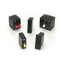
Circuit Breakers 30 A ONE POLE
Manufacturer
Carling Technologies
Series
Br
Type
Hydraulic/Magneticr
Specifications of BA1-B0-34-630-121-C
Product Type
Circuit Breakers
Current Rating
30 Amps
Voltage Rating
277 VoltsAC / 80 VoltsDC
Trip Time
0.6 s to 20 s
Mounting Style
Screw
Termination Style
Screw
Circuit Function
Series Trip (Current)
Color
White
Dielectric Strength
1.5 KV
Features
Control panels and marine equipment
Height
50.8 mm
Illuminated
No
Length
43.94 mm
Product
Hydraulic Magnetic Circuit Breakers
Width
39.62 mm
Number Of Poles
1 Pole
Actuator Type
Handle
Brand/series
B Series
Current, Rating
30 A
Dimensions
2.09"Lx0.755"Wx2"H
Frequency
50⁄60 Hz
Mounting Hole Size
0.156 "
Mounting Type
Panel
Standards
UL Recognized, CSA Certified
Termination
Quick Connect
Voltage, Rating
277/80 VAC/VDC
Lead Free Status / RoHS Status
Lead free / RoHS Compliant


62
B-Series Handle UL489A – Ordering Scheme
Notes:
1
2
3
4
5
6
7
8
1
Series
B
1 SERIES
B
2 ACTUATOR
A
B
S
T
3 POLES
1 One
4 CIRCUIT
B
5 AUXILIARY/ALARM SWITCH
0
1
2
3
6 FREQUENCY & DELAY
11
12
14
16
210
215
220
225
230
235
240
245
250
255
260
265
270
275
280
285
290
295
410
512
7 CURRENT RATING (AMPERES)
Actuator Code:
A: Handle tie pin spacer(s) and retainers provided unassembled with multi-pole units.
S: Handle moves to mid-position only upon electrical trip of the breaker.
T: Handle moves to mid-position and alarm switch activates only upon electrical trip of the
breaker.
On multi-pole breakers, one auxiliary switch is supplied, mounted in the extreme right
pole.
VDE Certification available with single pole breakers only. UL489A Listing available with
one and two pole breakers.
Screw Terminals are recommended on ratings greater than 20 amps. Ratings over 30
amps are only available with Terminal Codes 5, 9, G, H, M and Q.
Terminal Code 1 (Push-On) available up to 25 amps with TUV or VDE Certification and 30
amps with UL489A Listing, but is not recommended over 20 amps.
Terminal Codes 3, 5 and H (Bus Type) with TUV or VDE, are supplied with Lock Washers,
and Terminal Code M (M6 Threaded Stud) with TUV or VDE is supplied with Lock and
Flat Washers. These breakers are only TUV or VDE Certified when the washers are
used.
Single pole breakers with Terminal Code P (Printed Circuit Board) are available up to 30
amps with VDE Certification and 50 amps with UL489A Listing.
Terminal Code Q not available with VDE approvals.
Handle, one per pole
Handle, one per multipole unit
Mid-Trip Handle, one per pole
Mid-Trip Handle, one per pole & Alarm Switch
Series Trip (Current)
w/o Aux Switch
S.P.D.T., 0.093 Q.C. Term.
S.P.D.T., 0.110 Q.C. Term.
S.P.D.T., 0.139 Solder Lug
DC Ultra Short
DC Short
DC Medium
DC Long
2
Actuator
A 1
0.100
0.150
0.200
0.250
0.300
0.350
0.400
0.450
0.500
0.550
0.600
0.650
0.700
0.750
0.800
0.850
0.900
0.950
1.000
1.250
1
3
Poles
2 Two
4
415
517
420
522
527
430
435
440
445
450
455
460
465
470
475
480
485
490
495
610
–
2
4
Circuit
B 0
10.000
1.500
1.750
2.000
2.250
2.750
3.000
3.500
4.000
4.500
5.000
5.500
6.000
6.500
7.000
7.500
8.000
8.500
9.000
9.500
7
8
9
52
54
56
3 Three
5
Aux/Alarm
Switch
S.P.S.T., 0.110 Q.C.
Term.(Gold Contacts)
S.P.S.T., 0.187 Q.C. Term.
S.P.D.T., 0.187 Q.C. Term.
DC, Short,Hi-Inrush
DC, Medium, Hi-Inrush
DC, Long, Hi-Inrush
710
611
711
612
712
613
614
615
616
617
618
620
622
624
625
630
635
640
645
650
–
3
3
3
3
6
Frequency
& Delay
4 Four
14
10.500
11.000
11.500
12.000
12.500
13.000
14.000
15.000
16.000
17.000
18.000
20.000
22.000
24.000
25.000
30.000
35.000
40.000
45.000
50.000
–
7
Current Rating
450
8 TERMINAL
1
2
3
4
5
6
7
8
9 ACTUATOR COLOR
White
Black
Red
Green
Blue
Yellow
Gray
Orange
10 MOUNTING/BARRIERS
1
A
2
B
3
C
4
D
5
6
7
8
11 MAXIMUM APPLICATION RATING
M
12 AGENCY APPROVAL
T
K
J
5
6
6
Push-On 0.250 Tab (Q.C.)
Screw 8-32 w/upturned lugs
Screw 8-32 (Bus Type)
Screw 10-32 w/upturned lugs
Screw 10-32 (Bus Type)
Screw 8-32 w/upturned lugs
and 30° bend
Screw 8-32 (Bus Type) and
30° bend
Screw 10-32 w/upturned lugs
and 30° bend
MOUNTING STYLE
Threaded Insert, 2 per pole
6-32 x 0.195 inches
6-32 X 0.195 inches (multi-pole units only)
ISO M3 x 5mm
ISO M3 x 5mm (multi-pole units only)
Rectangular Adapter Plate with mounting centers of 2.062 inches
and Threaded insert, 2 per pole
6-32 x 0.225 inches
6-32 X 0.225 inches (multi-pole units only)
ISO M3 x 6.5mm
ISO M3 x 6.5mm (multi-pole units only)
Front panel Snap-In, 0.75” wide bezel
without Handleguard
without Handleguard (multi-pole units only)
Front panel Snap-In, 0.96” wide bezel
without Handleguard, 1-pole units 0.96” wide;
multipole units have .105“ bezel overhang on all sides
without Handleguard, 1-pole units 0.96” wide;
(multi-pole units only) .105“ bezel overhang on all sides
80 DC
UL489A Listed
UL489A Listed, VDE Certified
UL489A Listed, TUV Certified
–
4
8
Terminal
LEGEND
ON-OFF
B
D
G
J
L
N
Q
S
1 B 1
9
Actuator
Color
Dual
1
2
3
4
5
6
7
8
10
Mounting/
Barriers
9
B
F
G
H
M
P
Q
7
Legend Color
Black
White
White
White
White
Black
Black
Black
8
6
www.carlingtech.com
Screw 10-32 (Bus Type) and
30° bend
Screw M5 w/upturned lugs
Screw M5 w/upturned lugs
and 30° bend
Screw M5 (Bus Type)
and 30° bend
Screw M5 (Bus Type)
M6 Threaded Stud
Printed Circuit Board
Terminals
Push-In Stud
–
11
Max. Appl.
Rating
M
BARRIERS
no
yes
no
yes
no
yes
no
yes
no
yes
no
yes
12
Agency
Approval
T
Related parts for BA1-B0-34-630-121-C
Image
Part Number
Description
Manufacturer
Datasheet
Request
R

Part Number:
Description:
CIRCUIT BREAKER MAGNETIC 10A
Manufacturer:
Carling Technologies
Datasheet:

Part Number:
Description:
CIRCUIT BREAKER MAGNETIC 15A
Manufacturer:
Carling Technologies
Datasheet:

Part Number:
Description:
CIRCUIT BREAKER MAGNETIC 20A
Manufacturer:
Carling Technologies
Datasheet:

Part Number:
Description:
CIRCUIT BREAKER MAGNETIC 30A
Manufacturer:
Carling Technologies
Datasheet:

Part Number:
Description:
CIRCUIT BREAKER MAGNETIC 20A
Manufacturer:
Carling Technologies
Datasheet:
Part Number:
Description:
CIRC BRKR MGNTC 20A 1POLE
Manufacturer:
Carling Technologies

Part Number:
Description:
Circuit Breakers 5 A ONE POLE
Manufacturer:
Carling Technologies
Datasheet:
Part Number:
Description:
Circuit Breakers 2.5 A ONE POLE
Manufacturer:
Carling Technologies
Datasheet:
Part Number:
Description:
LIGHT INDICATOR GRN 12VDC PNLMNT
Manufacturer:
Carling Technologies
Part Number:
Description:
CONTURA ILL INDICATOR 12V RED
Manufacturer:
Carling Technologies
Part Number:
Description:
Current Regulator Diodes CURRENT REGULATOR DIODES 3.6mA
Manufacturer:
Carling Technologies
Part Number:
Description:
Rocker Switches
Manufacturer:
Carling Technologies
Datasheet: