B41112A6107M000 EPCOS Inc, B41112A6107M000 Datasheet
B41112A6107M000
Specifications of B41112A6107M000
Available stocks


Related parts for B41112A6107M000


B41112A6107M000 Summary of contents
Page 1
... Aluminum electrolytic capacitors SMD capacitors Series/Type: B41112 Date: November 2008 © EPCOS AG 2008. Reproduction, publication and dissemination of this publication, enclosures hereto and the information contained therein without EPCOS' prior express consent is prohibited. ...
Page 2
... I initial specified limit leak V (V DC 100 R < < After storage for 1000 the capacitors shall meet the requirement of load life test after reforming process. After test applied for 30 minutes hours before measurement 120 Hz 300 Hz 0.70 1.00 1.17 Page B41112 ...
Page 3
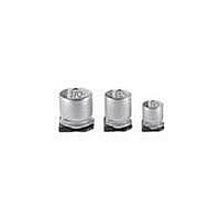
Dimensional drawings (mm) 4 5.4 ... 8 6.2: * Applies to 6.3 5.8 mm, 6 (mm ... 10 10: Case Terminal base board Minus pole Plus pole Case dimensions 4 5.4 d ...
Page 4
B41112 Standard series Layout recommendation Please read Cautions and warnings and Important notes at the end of this document (mm) 4.0 5.4 5.0 5.4 6.3 5.4 6.3 5.8 6.3 7.7 8.0 6.2 8.0 10.0 10.0 10.0 ...
Page 5
Overview of available types V (V DC) 4.0 R Case dimensions 5.4 100 5 5.4 150 6.3 5.4 220 6.3 5.4 6.3 5.8 330 ...
Page 6
B41112 Standard series Case dimensions 0.10 0.22 0.33 0.47 1.0 2.2 3.3 4 5 5.4 6.3 5.4 33 6.3 5.4 6.3 5.8 ...
Page 7
Technical data and ordering codes V C Case dimensions R R 120 Hz 100 5 150 6.3 220 6.3 220 6.3 330 6.3 330 6.3 470 6.3 ...
Page 8
B41112 Standard series Technical data and ordering codes V C Case dimensions R R 120 Hz 6 6.3 100 ...
Page 9
Technical data and ordering codes V C Case dimensions R R 120 6.3 47 6.3 47 6.3 56 6.3 ...
Page 10
... Page Ordering code 1 B41112A6104M000 2 B41112A6224M000 3 B41112A6334M000 5 B41112A6474M000 B41112A6105M000 B41112A6225M000 B41112A6335M000 B41112A6475M000 B41112B6475M000 B41112A6106M000 B41112B6106M000 B41112A6226M000 B41112B6226M000 B41112C6226M000 B41112B6336M000 B41112C6336M000 B41112A6336M000 B41112C6476M000 B41112A6476M000 B41112B6476M000 B41112A6566M000 B41112A6107M000 B41112B6107M000 B41112A6157M000 B41112A6227M000 ...
Page 11
Technical data and ordering codes V C Case dimensions R R 120 Hz 0.1 4 0.22 4 0.33 4 0.47 4 1.0 4 2.2 4 3 6.3 10 6.3 ...
Page 12
B41112 Standard series Mounting instructions Soldering Recommended conditions For reflow, use thermal conduction systems such as infrared radiation (IR) or hot blast. Vapor heat transfer systems (VPS) are not recommended. Observe proper soldering conditions (temperature, time, etc.). Do not exceed ...
Page 13
... Taping and packing Taping of SMD capacitors Case dimensions 4 5 (mm) W 12.0 P 8.0 F 5 5.8 2 Case dimensions 6.3 5 (mm) W 16.0 P 12.0 F 7 6.3 2 Please read Cautions and warnings and Important notes at the end of this document. Standard series 4 5.8 5 5.4 12.0 12 ...
Page 14
B41112 Standard series Reel packing Capacitor dimensions Quantity per reel d l (mm) pcs 2000 pcs 6 6.2 1000 pcs 500 pcs (mm ...
Page 15
... After such storage, the capacitor must be aged by applying the rated operating voltage for 6 – 8 hours before use. ...
Page 16
... Ensure that the terminal spacing matches the corresponding hole spacing on the PC board. 12 The aluminum case is not insulated from the cathode. Do not place a conductor under the aluminum capacitors on the PC board as this may cause a short circuit. The case and top of capacitors used in switched mode power supplies have a high-voltage-resistant heat shrink sleeve to ensure safe usage ...
Page 17
Important notes The following applies to all products named in this publication: 1. Some parts of this publication contain statements about the suitability of our products for certain areas of application. These statements are based on our knowledge of typical ...