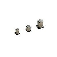
UCW1H221MNL1GS Nichicon, UCW1H221MNL1GS Datasheet

UCW1H221MNL1GS
Manufacturer Part Number
UCW1H221MNL1GS
Description
Aluminum Electrolytic Capacitors - SMD 50volts 220uF 105c 10X10
Manufacturer
Nichicon
Specifications of UCW1H221MNL1GS
Operating Temperature Range
- 25 C to + 105 C
Dimensions
10 mm Dia. x 10 mm L x 10.3 mm H
Product
Low Impedance Electrolytic Capacitors
Dissipation Factor Df
0.14
Leakage Current
3 uAmps
Load Life
7000 Hrs
Termination Style
SMD/SMT
Capacitance
220 uF
Tolerance
20 %
Voltage Rating
50 Volts
Lead Spacing
4.5 mm
Ripple Current
670 mAmps
Capacitance Tolerance
± 20%
Life Time @ Temperature
7000 Hours @ 105°C
Height
10mm
Diameter
10mm
Capacitor Case Style
Radial
Capacitor Mounting
SMD
Rohs Compliant
Yes
Lead Free Status / RoHS Status
Lead free / RoHS Compliant
Available stocks
Company
Part Number
Manufacturer
Quantity
Price
Company:
Part Number:
UCW1H221MNL1GS
Manufacturer:
NICHICON
Quantity:
20 000
Company:
Part Number:
UCW1H221MNL1GS
Manufacturer:
NICHICON
Quantity:
44 000
ALUMINUM ELECTROLYTIC CAPACITORS
UG
A
B
C
E
H
L
Item
Category Temperature Range
Rated Voltage Range
Rated Capacitance Range
Capacitance Tolerance
Leakage Current
Tangent of loss angle (tan )
Stability at Low Temperature
Endurance
Shelf Life
Marking
Trade mark
Capacitance
D
Chip Type , higher capacitance in larger case sizes ( 12.5, 16, 18, 20)
Designed for surface mounting on high density PC board.
Applicable to automatic mounting machine fed with carrier tape and tray.
Compliant to the RoHS directive (2002/95/EC).
Specifications
Chip Type
Dimension table in next page.
12.5 13.5
1.0 to 1.4
13.6
13.6
13.5
4.8
4.0
1.0 to 1.4
12.5
13.6
13.6
16.0
4.8
4.0
Voltage
16.
Series
series
Chip Type, Higher Capacitance Range
Lot No.
1.0 to 1.4
12.5
13.6
13.6
21.0
4.8
4.0
Pressure
relief vent
21.
– 40 to +85°C
6.3 to 450V
4.7 to 10000µF
± 20% at 120Hz, 20°C
Black print on the case top.
For capacitance of more than 1000µF, add 0.02 for every increase of 1000µF.
The specifications listed at right shall be met when the
capacitors are restored to 20°C after the rated voltage is
applied for 2000 hours at 85°C.
After storing the capacitors under no load at 85°C for 1000 hours and then performing voltage treatment based on JIS C 5101-4
clause 4.1 at 20°C, they shall meet the specified values for the endurance characteristics listed above.
1.0 to 1.4
16
Rated voltage (V)
Impedance ratio
ZT / Z20 (MAX.)
17.1
17.1
16.5
5.4
6.3
16.5.
tan
Plastic platform
Rated voltage (V)
1.0 to 1.4
(MAX.)
Rated voltage (V)
L 1.0
16
17.1
17.1
21.5
5.4
6.3
21.5.
—
0.3 MAX.
1.0 to 1.4
18
Z– 25°C / Z+20°C
Z– 40°C / Z+20°C
19.1
19.1
16.5
6.4
6.3
16.5.
0.28
6.3
1.0 to 1.4
18
19.1
19.1
21.5
6.4
6.3
After 1 minute's application of rated voltage, leakage current is not more
than 0.03CV or 4 (µA), whichever is greater.
21.5.
C 0.2
0.24
H
10
1.3 to 1.7
20
21.1
21.1
16.5
6.2
8.8
6.3
12
16.5.
5
0.20
1.3 to 1.7
16
20
21.1
21.1
21.5
Negative
6.2
8.8
10
10
21.5.
4
Positive
(mm)
Performance Characteristics
0.16
25
16
3
8
High
Temperature
UG
6.3 to 100
U
UJ
Type numbering system (Example : 50V 330
1
Capacitance change
tan
Leakage current
U
2
G
0.14
25
2
5
3
35
1
4
H
5
35
2
4
0.12
3
6
50
Measurement frequency : 120Hz, Temperature : 20°C
3
7
Within ±20% of the initial capacitance value
200% or less than the initial specified value
Less than or equal to the initial specified value
1
8
50
2
3
M
9
0.10
63
Capacitance Tolerance ( 20% )
N
10
Rated capacitance ( 330 F)
63
Q
2
3
11
Measurement frequency: 120Hz
12 13
1
0.08
100
Rated voltage ( 50V )
(1 minute's)
I = 0.04CV+100 ( µA) max.
M S
100
Size code
2
3
14
Series name
160 to 250
160 to 250
160 to 450
0.20
CAT.8100Y
µ
Type
F)
3
6
Taping
Tray
12.5 to 18
400
Package code
Configuration
20
400
D
0.25
10
•
6
•
450
450
MS
Code
ZD
NQ
RQ
Related parts for UCW1H221MNL1GS
UCW1H221MNL1GS Summary of contents
Page 1
... ALUMINUM ELECTROLYTIC CAPACITORS UG Chip Type, Higher Capacitance Range series Chip Type , higher capacitance in larger case sizes ( 12.5, 16, 18, 20) Designed for surface mounting on high density PC board. Applicable to automatic mounting machine fed with carrier tape and tray. Compliant to the RoHS directive (2002/95/EC). Specifications Item – ...
Page 2
... ALUMINUM ELECTROLYTIC CAPACITORS UG series Dimensions V 6.3 (µF) 0J Cap. Code 220 221 330 331 470 471 1000 102 12.5 2200 222 12.5 16.0 890 12.5 3300 332 16 16.5 1200 16 4700 472 16 16.5 1400 18 6800 682 18 16.5 1650 18 10000 103 18 21.5 2000 100 (µ ...


