561R10TCCT10 Vishay, 561R10TCCT10 Datasheet

Ceramic Disc Capacitors 1Kvolts 100pF 5% .25LS NPO

561R10TCCT10

Manufacturer Part Number
561R10TCCT10
Description
Ceramic Disc Capacitors 1Kvolts 100pF 5% .25LS NPO
Manufacturer
Vishay
Series
561Rr
Datasheet

Specifications of 561R10TCCT10

Voltage Rating
1 KVolts
Operating Temperature Range
- 55 C to + 105 C
Termination Style
Radial
Product
Ceramic Disc Capacitors - Other Various
Dimensions
14.2 mm Dia. x 4 mm W
Dissipation Factor Df
0.1
Capacitance
100 pF
Tolerance
5 %
Temperature Coefficient
C0G (NP0)
Lead Spacing
9.5 mm
Dielectric Characteristic
C0G / NP0
Capacitance Tolerance
± 5%
Capacitor Case Style
Radial Leaded
No. Of Pins
2
Rohs Compliant
Yes
Lead Free Status / RoHS Status
Lead free / RoHS Compliant
INSULATION RESISTANCE
Min. 1000 ΩF or 50 000 MΩ
TOLERANCE ON CAPACITANCE
± 5 %
DISSIPATION FACTOR
0.1 % max. at 1 MHz; 1 V
CATEGORY TEMPERATURE RANGE
(- 55 to + 125) °C
CLIMATIC CATEGORY ACC. TO EN60068-1
55/125/21
OPERATING TEMPERATURE RANGE
(- 55 to + 105) °C
Document Number: 23108
Revision: 04-Jun-09
max.
LEAD OFFSET ‘LO” (NOMINAL)
D
Fig. 1
Fig. 2
max.
D
1000 VDC
1.250" min. (32)
1.250" min. (32)
0.125" max. (3)
0.125" max. (3)
Lower Voltage Ceramic Disc Capacitors
1000 VDC Precision Capacitors
for technical questions, contact:
0.050" (1.3 mm)
LS
LS
max.
T
max.
T
LO
LO
ceramitesupport@vishay.com
FEATURES
• Ultra stable over temperature and voltage
• Used when the ultimate in stability is required
• Radial leads
APPLICATIONS
• Temperature compensating
• Resonant circuit
DESIGN
The capacitors consist of a ceramic disc of which both sides
are silver-plated. Connection leads are made of tinned
copper or tinned copper clad steel having diameters of
0.020" (0.51 mm) or 0.025" (0.64 mm).
The capacitors may be supplied with radial kinked or straight
leads having lead spacing of 0.250" (6.35 mm) or 0.375"
(9.5 mm).
Coating is made of flame retardant epoxy resin in
accordance with “UL 94 V-0”.
CAPACITANCE RANGE
1.0 pF to 680 pF
RATED VOLTAGE
1000 VDC
DIELECTRIC STRENGTH BETWEEN LEADS
Component test:
2500 VDC, 2 s
CERAMIC DIELECTRIC
C0K, C0G, U2J, M3K, S3N (Class 1)
Vishay Cera-Mite
561R Series
www.vishay.com
1

Related parts for 561R10TCCT10

561R10TCCT10 Summary of contents

Page 1

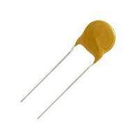
... Coating is made of flame retardant epoxy resin accordance with “UL 94 V-0”. max. CAPACITANCE RANGE 1 680 pF RATED VOLTAGE 0.050" (1.3 mm) 1000 VDC DIELECTRIC STRENGTH BETWEEN LEADS Component test: 2500 VDC CERAMIC DIELECTRIC C0K, C0G, U2J, M3K, S3N (Class 1) ceramitesupport@vishay.com 561R Series Vishay Cera-Mite www.vishay.com 1 ...

Page 2

... Document Number: 23108 Revision: 04-Jun-09 CODE ...

Page 3

... Vishay product could result in personal injury or death. Customers using or selling Vishay products not expressly indicated for use in such applications their own risk and agree to fully indemnify and hold Vishay and its distributors harmless from and against any and all claims, liabilities, expenses and damages arising or resulting in connection with such use or sale, including attorneys fees, even if such claim alleges that Vishay or its distributor was negligent regarding the design or manufacture of the part ...

Related keywords