DEBB33D102KN2A Murata, DEBB33D102KN2A Datasheet - Page 68
DEBB33D102KN2A
Manufacturer Part Number
DEBB33D102KN2A
Description
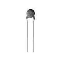
Ceramic Disc Capacitors 1000pF 2000volts B 10%
Manufacturer
Murata
Series
DEBr
Datasheet
1.DEA1X3A101JN2A.pdf
(83 pages)
Specifications of DEBB33D102KN2A
Voltage Rating
2 KVolts
Operating Temperature Range
- 25 C to + 85 C
Termination Style
Radial
Product
High Voltage Ceramic Disc Capacitors
Dimensions
8 mm Dia.
Capacitance
1000 pF
Tolerance
10 %
Temperature Coefficient
B
Lead Spacing
5 mm
Lead Free Status / RoHS Status
Lead free / RoHS Compliant


11
!Note
Operating and Storage Environment
1. Vibration and Impact
Vibration and Impact
66
2. Soldering
The insulating coating of capacitors does not form a
perfect seal; therefore, do not use or store
capacitors in a corrosive atmosphere, especially
where chloride gas, sulfide gas, acid, alkali, salt
or the like are present. Also, avoid exposure to
moisture. Before cleaning, bonding or molding this
product, verify that these processes do not affect
product quality by testing the performance of a
cleaned, bonded or molded product in the intended
equipment. Store the capacitors where the
temperature and relative humidity do not exceed -10
to 40 degrees centigrade and 15 to 85%.
Do not expose a capacitor or its lead wires to
excessive shock or vibration during use.
Excessive shock or vibration may cause fatigue
destruction of lead wires mounted on the circuit
board.
Please take measures to hold a capacitor on the
circuit boards by adhesive, molding resin or another
coating.
High Voltage Ceramic Capacitors !Caution
!Caution (Storage and Operating Condition)
!Caution (Soldering and Mounting)
Do not expose a capacitor or its lead wires to
excessive shock or vibration during use.
Excessive shock or vibration may cause fatigue
destruction of lead wires mounted on the circuit
board.
Please take measures to hold a capacitor on the
circuit boards by adhesive, molding resin or another
coating.
Please confirm there is no influence of holding
measures on the product with the intended equipment.
When soldering this product to a PCB/PWB, do not
exceed the solder heat resistance specification of
the capacitor. Subjecting this product to excessive
heating could melt the internal junction solder and
may result in thermal shocks that can crack the
ceramic element.
Soldering the capacitor with a soldering iron should
be performed in following conditions.
!Caution (Handling)
Temperature of iron-tip: 400 degrees C. max.
Soldering iron wattage: 50W max.
Soldering time: 3.5 sec. max.
• Please read rating and !CAUTION (for storage, operating, rating, soldering, mounting and handling) in this catalog to prevent smoking and/or burning, etc.
• This catalog has only typical specifications because there is no space for detailed specifications. Therefore, please review our product specifications or consult the approval sheet for product specifications before ordering.
FAILURE TO FOLLOW THE ABOVE CAUTIONS MAY
RESULT, WORST CASE, IN A SHORT CIRCUIT
AND CAUSE FUMING OR PARTIAL DISPERSION
WHEN THE PRODUCT IS USED.
3. Bonding, Resin Molding and Coating
FAILURE TO FOLLOW THE ABOVE CAUTIONS MAY
RESULT, WORST CASE, IN A SHORT CIRCUIT
AND CAUSE FUMING OR PARTIAL DISPERSION
WHEN THE PRODUCT IS USED.
4. Treatment after Bonding, Resin Molding and Coating
FAILURE TO FOLLOW THE ABOVE CAUTIONS MAY
RESULT, WORST CASE, IN A SHORT CIRCUIT
AND CAUSE FUMING OR PARTIAL DISPERSION
WHEN THE PRODUCT IS USED.
Use capacitors within 6 months after delivery.
Check the solderability after 6 months or more.
Please confirm there is no influence of holding
measures on the product with the intended equipment.
For bonding, molding or coating this product, verify
that these processes do not affect the quality of the
capacitor by testing the performance of the bonded,
molded or coated product in the intended equipment.
When the amount of applications, dryness/hardening
conditions of adhesives and molding resins containing
organic solvents (ethyl acetate, methyl ethyl ketone,
toluene, etc). are unsuitable, the outer coating resin
of a capacitor is damaged by the organic solvents and
it may result, worst case, in a short circuit.
The variation in thickness of adhesive, molding resin
or coating may cause outer coating resin cracking
and/or ceramic element cracking of a capacitor in a
temperature cycling.
When the outer coating is hot (over 100 degrees C.)
after soldering, it becomes soft and fragile.
Therefore, please be careful not to give it mechanical
stress.
C85E.pdf
Jul.13,2011
Related parts for DEBB33D102KN2A
Image
Part Number
Description
Manufacturer
Datasheet
Request
R

Part Number:
Description:
Murata Microblower 20x20 DCDC Driver Board - Samples Only
Manufacturer:
Murata
Part Number:
Description:
357-036-542-201 CARDEDGE 36POS DL .156 BLK LOPRO
Manufacturer:
Murata
Datasheet:
Part Number:
Description:
Manufacturer:
Murata
Datasheet:
Part Number:
Description:
Manufacturer:
Murata
Datasheet:
Part Number:
Description:
Manufacturer:
Murata
Datasheet:
Part Number:
Description:
Manufacturer:
Murata
Datasheet:
Part Number:
Description:
Manufacturer:
Murata
Datasheet:
Part Number:
Description:
Manufacturer:
Murata
Datasheet:
Part Number:
Description:
Manufacturer:
Murata
Datasheet:
Part Number:
Description:
BLM21BD751SN1On-Board Type (DC) EMI Suppression Filters
Manufacturer:
Murata
Datasheet:
Part Number:
Description:
BLM15AG100SN1On-Board Type (DC) EMI Suppression Filters
Manufacturer:
Murata
Datasheet:
Part Number:
Description:
NFE31PT222Z1E9On-Board Type (DC) EMI Suppression Filters
Manufacturer:
Murata
Datasheet:
Part Number:
Description:
Chip Coil
Manufacturer:
Murata
Datasheet:
Part Number:
Description:
Chip Coil
Manufacturer:
Murata
Datasheet: